HA5024IBZ Intersil, HA5024IBZ Datasheet - Page 4
HA5024IBZ
Manufacturer Part Number
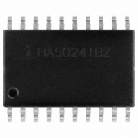
HA5024IBZ
Description
IC OPAMP QUAD 125MHZ 20-SOIC
Manufacturer
Intersil
Datasheet
1.HA5024IBZ.pdf
(16 pages)
Specifications of HA5024IBZ
Applications
Current Feedback
Number Of Circuits
4
-3db Bandwidth
125MHz
Slew Rate
350 V/µs
Current - Supply
7.5mA
Current - Output / Channel
20mA
Voltage - Supply, Single/dual (±)
±4.5 V ~ 18 V
Mounting Type
Surface Mount
Package / Case
20-SOIC (0.300", 7.50mm Width)
Peak Reflow Compatible (260 C)
Yes
Rohs Compliant
Yes
Lead Free Status / RoHS Status
Lead free / RoHS Compliant
Available stocks
Company
Part Number
Manufacturer
Quantity
Price

Part Number:
HA5024IBZ
Manufacturer:
INFTEL
Quantity:
20 000


Electrical Specifications
NOTES:
10. R
11. A. Production Tested; B. Typical or Guaranteed Limit based on characterization; C. Design Typical for information only.
12. V
13. V
14. V
15. Measured with a VM700A video tester using an NTC-7 composite VITS.
16. V
AC CHARACTERISTICS (A
Slew Rate
Full Power Bandwidth
Rise Time
Fall Time
Propagation Delay
Overshoot
-3dB Bandwidth
Settling Time to 1%
Settling Time to 0.25%
Gain Flatness
AC CHARACTERISTICS (A
Slew Rate
Full Power Bandwidth
Rise Time
Fall Time
Propagation Delay
Overshoot
-3dB Bandwidth
Settling Time to 1%
Settling Time to 0.1%
VIDEO CHARACTERISTICS
Differential Gain (Note 15)
Differential Phase (Note 15)
5. V
6. R
7. V
8. V
9.
considered disabled when -10mV ≤ V
considered disabled when the supply current has decreased by at least 0.5mA.
FPBW
CM
IN
OUT
IN
IN
IN
OUT
L
L
= 100Ω, V
= 100Ω, V
= 0V. This is the maximum current that can be pulled out of the Disable pin with the HA5024 remaining enabled. The HA5024 is
= +2V, DISABLE = +5V to 0V. Measured from the 50% point of DISABLE to V
= +2V, DISABLE = 0V to +5V. Measured from the 50% point of DISABLE to V
= 0V, Force V
= ±2.5V. At -40°C Product is tested at V
switches from -2V to +2V, or from +2V to -2V. Specification is from the 25% to 75% points.
= ±2.5V. At -40°C Product is tested at V
=
---------------------------- - ; V
2πV PEAK
Slew Rate
PARAMETER
IN
OUT
= 2.5V. This is the minimum current which must be pulled out of the Disable pin in order to disable the output. The output is
OUT
= 1V. Measured from 10% to 90% points for rise/fall times; from 50% points of input and output for propagation delay.
from 0V to ±2.5V, t
PEAK
V
V
= +2, R
= +10, R
4
V
=
SUPPLY
F
2V
F
= 681Ω)
OUT
= 383Ω)
.
= ±5V, R
R
≤ +10mV.
Note 8
Note 9
Note 10
Note 10
Note 10
V
2V Output Step
2V Output Step
5MHz
20MHz
Note 8
Note 9
Note 10
Note 10
Note 10
V
2V Output Step
2V Output Step
R
R
= t
OUT
OUT
L
L
CM
= 150Ω
= 150Ω
OUT
F
TEST CONDITIONS
= 50ns, DISABLE = 0V.
= ±2.25V because short test duration does not allow self heating.
= 100mV
= 100mV
F
= ±2.25V because short test duration does not allow self heating.
= 1kΩ, A
V
= +1, R
HA5024
L
= 400Ω, C
(NOTE 11)
LEVEL
TEST
B
B
B
B
B
B
B
B
B
B
B
B
B
B
B
B
B
B
B
B
B
B
L
≤ 10pF,Unless Otherwise Specified (Continued)
OUT
OUT
= 0V.
= 2V.
TEMP.
(°C)
25
25
25
25
25
25
25
25
25
25
25
25
25
25
25
25
25
25
25
25
25
25
MIN
350
28
-
-
-
-
-
-
-
-
-
-
-
-
-
-
-
-
-
-
-
-
TYP
0.02
0.07
0.03
0.03
475
100
475
130
1.8
26
12
95
50
38
65
75
6
6
6
8
9
9
MAX
-
-
-
-
-
-
-
-
-
-
-
-
-
-
-
-
-
-
-
-
-
-
February 8, 2006
Degrees
UNITS
V/µs
MHz
MHz
V/µs
MHz
MHz
dB
dB
ns
ns
ns
ns
ns
ns
ns
ns
ns
ns
%
%
%
3550.6
Related parts for HA5024IBZ
Image
Part Number
Description
Manufacturer
Datasheet
Request
R

Part Number:
Description:
Quad 125MHz Video Current Feedback Amplifier with Disable
Manufacturer:
Intersil Corporation
Datasheet:
Part Number:
Description:
Intersil Corporation [CMOS Serial Controller Interface]
Manufacturer:
Intersil Corporation
Datasheet:
Part Number:
Description:
Manufacturer:
Intersil Corporation
Datasheet:
Part Number:
Description:
357-036-542-201 CARDEDGE 36POS DL .156 BLK LOPRO
Manufacturer:
Intersil Corporation
Datasheet:
Part Number:
Description:
1024-Word x 4-Bit LSI Static RAM
Manufacturer:
Intersil Corporation
Datasheet:
Part Number:
Description:
General Purpose NPN Transistor Arrays FN341.4
Manufacturer:
Intersil Corporation
Datasheet:
Part Number:
Description:
CMOS 16-Bit Microprocessor
Manufacturer:
Intersil Corporation
Datasheet:
Part Number:
Description:
Manufacturer:
Intersil Corporation
Datasheet:
Part Number:
Description:
Manufacturer:
Intersil Corporation
Datasheet:
Part Number:
Description:
Manufacturer:
Intersil Corporation
Datasheet:
Part Number:
Description:
Manufacturer:
Intersil Corporation
Datasheet:
Part Number:
Description:
CMOS 6-Bit Latch and Decoder Memory Interfaces
Manufacturer:
Intersil Corporation
Datasheet:
Part Number:
Description:
CA3046General Purpose NPN Transistor Arrays
Manufacturer:
Intersil Corporation
Datasheet:
Part Number:
Description:
Manufacturer:
Intersil Corporation
Datasheet:
Part Number:
Description:
TR909 DLC/FLC SLIC with Low Power Standby
Manufacturer:
Intersil Corporation
Datasheet: