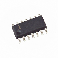
ISL59442IBZ-T13 Intersil, ISL59442IBZ-T13 Datasheet

ISL59442IBZ-T13
Specifications of ISL59442IBZ-T13
Related parts for ISL59442IBZ-T13
ISL59442IBZ-T13 Summary of contents
Page 1
... ISL59442IBZ-T7 (Note) 59442IBZ ISL59442IBZ-T13 (Note) 59442IBZ NOTE: Intersil Pb-free plus anneal products employ special Pb-free material sets; molding compounds/die attach materials and 100% matte tin plate termination finish, which are RoHS compliant and compatible with both SnPb and Pb-free soldering operations. Intersil Pb-free products are MSL classified at Pb-free peak reflow temperatures that meet or exceed the Pb-free requirements of IPC/JEDEC J STD-020 ...
Page 2
Absolute Maximum Ratings (T A Supply Voltage (V+ to V-). . . . . . . . . . . . . . . . . . . . . . . . . . . . . . . ...
Page 3
Electrical Specifications V+ = +5V -5V, GND = 0V, T Unless Otherwise Specified (Continued) PARAMETER DESCRIPTION PSRR Power Supply Rejection Ratio ISO Channel Isolation SWITCHING CHARACTERISTICS V Channel-to-Channel Switching Glitch V GLITCH HIZ Switching Glitch t Channel Switching ...
Page 4
Typical Performance Curves OUT P 25Ω 23.6pF INCLUDES 1.6pF L -4 BOARD CAPACITANCE C = 28.6pF L -5 0.001 0.01 FREQUENCY ...
Page 5
Typical Performance Curves 200mV 23.6pF 25Ω S -10 -20 -30 -40 -50 PSRR (V+) -60 PSRR (V-) -70 -80 0.3M 1M 10M FREQUENCY (Hz) FIGURE 9. PSRR CHANNELS ...
Page 6
Typical Performance Curves S0 OUT 20ns/DIV FIGURE 15. CHANNEL TO CHANNEL SWITCHING GLITCH 23.6pF HIZ OUT 20ns/DIV FIGURE 17. HIZ SWITCHING GLITCH ...
Page 7
Typical Performance Curves JEDEC JESD51-7 HIGH EFFECTIVE THERMAL CONDUCTIVITY TEST BOARD 1.4 1.136W 1.2 1 0.8 0.6 0.4 0 AMBIENT TEMPERATURE (°C) FIGURE 21. PACKAGE POWER DISSIPATION vs AMBIENT TEMPERATURE Pin Descriptions PIN NUMBER ...
Page 8
AC Test Circuits ISL59442 50Ω 2pF 75Ω FIGURE 23A. TEST CIRCUIT WITH OPTIMAL OUTPUT LOAD V IN 50Ω 75Ω FIGURE 23C. BACKLOADED TEST CIRCUIT FOR VIDEO CABLE APPLICATION. BANDWIDTH AND LINEARITY FOR RL LESS THAN ...
Page 9
Application Information General The ISL59442 is a 4:1 mux that is ideal as a matrix element in high performance switchers and routers. The ISL59442 is optimized to drive a 2pF in parallel with a 500Ω load. The capacitance can be ...
Page 10
PC Board Layout The frequency response of this circuit depends greatly on the care taken in designing the PC board. The following are recommendations to achieve optimum high frequency performance from your PC board. • The use of low inductance ...
Page 11
... Accordingly, the reader is cautioned to verify that data sheets are current before placing orders. Information furnished by Intersil is believed to be accurate and reliable. However, no responsibility is assumed by Intersil or its subsidiaries for its use; nor for any infringements of patents or other rights of third parties which may result from its use ...


