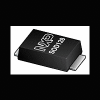
PMEG4010EP NXP Semiconductors, PMEG4010EP Datasheet - Page 9

PMEG4010EP
Manufacturer Part Number
PMEG4010EP
Description
Planar Maximum Efficiency General Application (MEGA) Schottky barrier rectifier with anintegrated guard ring for stress protection, encapsulated in a SOD128 small and flat leadSurface-Mounted Device (SMD) plastic package
Manufacturer
NXP Semiconductors
Datasheet
1.PMEG4010EP.pdf
(14 pages)
Available stocks
Company
Part Number
Manufacturer
Quantity
Price
Company:
Part Number:
PMEG4010EP
Manufacturer:
NXP
Quantity:
15 000
Company:
Part Number:
PMEG4010EP
Manufacturer:
NXP
Quantity:
12 000
Part Number:
PMEG4010EPK
Manufacturer:
NXP/恩智浦
Quantity:
20 000
Company:
Part Number:
PMEG4010EPЈ¬115
Manufacturer:
NXP
Quantity:
9 000
NXP Semiconductors
8. Test information
9. Package outline
PMEG4010EP_2
Product data sheet
8.1 Quality information
I
The current ratings for the typical waveforms as shown in
calculated according to the equations:
This product has been qualified in accordance with the Automotive Electronics Council
(AEC) standard Q101 - Stress test qualification for discrete semiconductors, and is
suitable for use in automotive applications.
RMS
Fig 13. Duty cycle definition
Fig 14. Package outline SOD128
=
I
F AV
(
)
at DC, and
All information provided in this document is subject to legal disclaimers.
Dimensions in mm
Rev. 02 — 15 April 2010
5.0
4.4
I
RMS
4.0
3.6
P
=
I
M
×
t
1
2.7
2.3
1.9
1.6
I
F AV
δ
(
t
2
with I
1 A low V
)
duty cycle δ =
1
2
=
I
RMS
M
006aaa812
×
δ
defined as RMS current.
F
MEGA Schottky barrier rectifier
t
t
t
with I
1
2
Figure
1.1
0.9
PMEG4010EP
0.22
0.10
M
defined as peak current,
07-09-12
9, 10,
0.6
0.3
© NXP B.V. 2010. All rights reserved.
11
and
12
are
9 of 14


