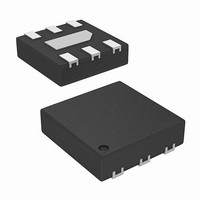
ISL28197FRUZ-T7 Intersil, ISL28197FRUZ-T7 Datasheet

ISL28197FRUZ-T7
Specifications of ISL28197FRUZ-T7
Related parts for ISL28197FRUZ-T7
ISL28197FRUZ-T7 Summary of contents
Page 1
... ISL28196FHZ-T7* (Note 1) ISL28196FRUZ-T7* (Note 2) ISL28197FHZ-T7* (Note 1) ISL28197FRUZ-T7* (Note 2) *Please refer to TB347 for details on reel specifications. NOTES: 1. These Intersil Pb-free plastic packaged products employ special Pb- free material sets, molding compounds/die attach materials, and 100% matte tin plate plus anneal (e3 termination finish, which is RoHS compliant and compatible with both SnPb and Pb-free soldering operations) ...
Page 2
... Thermal Resistance (Typical, Note SOT-23 Package . . . . . . . . . . . . . . . . . . . . . . . 6 Ld µTDFN Package . . . . . . . . . . . . . . . . . . . . . . . Output Short-Circuit Duration . . . . . . . . . . . . . . . . . . . . . . .Indefinite Ambient Operating Temperature Range . . . . . . . . .-40°C to +125°C Storage Temperature Range . . . . . . . . . . . . . . . . . .-65°C to +150°C Operating Junction Temperature . . . . . . . . . . . . . . . . . . . . . +125°C Pb-Free Reflow Profile .see link below http://www.intersil.com/pbfree/Pb-FreeReflow.asp = 0V 2.5V +25°C, unless otherwise specified. Boldface limits apply over -40°C to ...
Page 3
Electrical Specifications +125°C. (Continued) PARAMETER DESCRIPTION TIMING t ± ISL28196 Propagation Delay Low to High and High to Low ± ISL28197 Propagation Delay Low to High and High to Low C PD ...
Page 4
Typical Performance Curves 350 10kΩ L 300 250 OD = 20mV 200 150 100 100mV 0 1.5 2.0 2.5 3.0 3.5 SUPPLY VOLTAGE (V) FIGURE 5. ISL28196 PROP DELAY vs SUPPLY VOLTAGE (FALLING EDGE) ...
Page 5
Typical Performance Curves 10Ω SINKING 1.0 1.5 2.0 2.5 3.0 3.5 SUPPLY VOLTAGE (V) FIGURE 11. ISL28196 SHORT CIRCUIT CURRENT vs SUPPLY VOLTAGE 3.0 2.8 2.6 2.4 2.2 2.0 1.8 1.6 ...
Page 6
Typical Performance Curves 1000 950 900 850 800 750 700 650 600 1.5 2.0 2.5 3.0 3.5 SUPPLY VOLTAGE (V) FIGURE 17. ISL28196 ENABLE LOW TO OUTPUT TURN-OFF TIME vs SUPPLY VOLTAGE 4 1000 MAX 4.0 3.5 3.0 ...
Page 7
Typical Performance Curves 120 N = 1000 100 80 MAX 60 MEDIAN 40 20 MIN 0 -40 - TEMPERATURE (°C) FIGURE 23. ISL28196 I vs TEMPERATURE, BIAS ±2. ...
Page 8
Typical Performance Curves 105 N = 1000 MAX 100 95 MEDIAN 90 85 MIN -40 - TEMPERATURE (°C) FIGURE 29. ISL28196 CMRR vs TEMPERATURE, VCM = 0. ...
Page 9
Typical Performance Curves 1000 45 40 MAX 35 30 MEDIAN 25 20 MIN 15 -40 - TEMPERATURE (°C) FIGURE 35. ISL28196 V LOW vs TEMPERATURE, OUT ±2.5V ...
Page 10
Typical Performance Curves 8 1000 7.5 MAX 7.0 6.5 6.0 MEDIAN 5.5 5.0 MIN 4.5 -40 - TEMPERATURE (°C) FIGURE 41. ISL28196 FALL TIME vs TEMPERATURE 20 Pin ...
Page 11
Break-Before-Make Operation of the Output The output circuit has a break-before-make response. This means that the P-Channel turns off before the N-Channel turns on during a high to low transition of the output (reference Figure 43). Likewise, the N-Channel turns ...
Page 12
Power Dissipation It is possible to exceed the +150°C maximum junction temperatures under certain load and power-supply conditions therefore important to calculate the maximum junction temperature (T JMAX to determine if power supply voltages, load conditions, or package ...
Page 13
... Warpage shall not exceed 0.10mm. 4. Package length/package width are considered as special characteristics. 5. JEDEC Reference MO-229 For additional information, to assist with the PCB Land Pattern SEATING Design effort, see Intersil Technical Brief TB389. PLANE 0.127 +0.058 -0.008 TERMINAL THICKNESS 2.00 MILLIMETERS MIN ...
Page 14
... Accordingly, the reader is cautioned to verify that data sheets are current before placing orders. Information furnished by Intersil is believed to be accurate and reliable. However, no responsibility is assumed by Intersil or its subsidiaries for its use; nor for any infringements of patents or other rights of third parties which may result from its use ...


