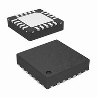
ISL59920IRZ Intersil, ISL59920IRZ Datasheet - Page 13

ISL59920IRZ
Manufacturer Part Number
ISL59920IRZ
Description
IC ANLG VID LINE TRPL 20-QFN
Manufacturer
Intersil
Type
Video Delay Liner
Datasheet
1.ISL59922IRZ.pdf
(16 pages)
Specifications of ISL59920IRZ
Applications
RGB Video Signals
Mounting Type
Surface Mount
Package / Case
20-VQFN Exposed Pad, 20-HVQFN, 20-SQFN, 20-DHVQFN
Lead Free Status / RoHS Status
Lead free / RoHS Compliant
Available stocks
Company
Part Number
Manufacturer
Quantity
Price
Company:
Part Number:
ISL59920IRZ-T7
Manufacturer:
Intersil
Quantity:
1 050
Offset Compensation
To counter the effects of offset, the ISL5992x incorporates an
offset compensation circuit that reduces the offset to less than
±25mV. An offset correction cycle is triggered by the rising
edge of the SENABLE pin after writing a delay word to any of
the 3 channels. The offset calibration starts about 500ns after
the SENABLE rising edge to allow the ISL5992x time to settle
(electrically and thermally) to the new delay setting. It lasts
about 2.5µs, for a total offset correction time of 3.0µs. During
calibration, the ISL5992x’s inputs are internally shorted
together (however the characteristics of the ISL5992x’s
differential input pins stay the same), and the offset of the
output stage is adjusted until it has been minimized.
In addition to automatically triggering after a delay change
(or any register write), an additional offset calibration may be
initiated at any time, such as:
• When the die temperature changes. Applying power to the
• When the ambient temperature changes. If you are
• After a CENABLE (Chip Enable) cycle. The CENABLE pin
• After a gain change (X2 pin changes state). The systematic
ISL5992x will cause the die temperature to quickly increase
then slowly settle over 20 to 30ns. Because the ISL5992x
powers-down unused delay stages (to minimize power
consumption), the die temp will also change and settle after
a delay change. Initiating an offset 20ns (or longer,
depending on the thermal characteristics of the system)
after power-on or a delay change will minimize the offset in
normal operation thereafter.
monitoring the temperature, initiate a calibration every time
the temperature shifts by 5 to 10 degrees. If you are not
monitoring temperature, initiate a calibration periodically, as
expected by the environment the device is in.
may be taken low to put the ISL5992x in a low power
standby mode to conserve power when not needed. When
the CENABLE pin goes high to exit this low power mode,
the ISL5992x will recall the delay settings but it will not
recall the correct offset calibration settings, so to maintain
low offset, a write to the delay register is required after a
CENABLE cycle. Offset errors may be as large as
±200mV coming out of standby mode - recalibration is a
necessity. For best performance, initiate an additional
calibration again once the die temperature has settled (20
to 30ns after coming out of standby).
offset is different for a gain of x1 vs. a gain of x2, so an
offset calibration is recommended after a gain change.
However in a typical application the gain is permanently
fixed at x1 or x2, so this is not usually a concern.
13
ISL59920, ISL59921, ISL59922, ISL59923
Offset Calibration with Sync-On-Video
The offset correction mechanism temporarily disconnects
the input signals to perform the offset calibration. This
introduces several discontinuities in the video signal, as
shown in Figure 10 on page 7:
• 200-300mV spike when calibration is engaged
• Successive-approximation offset null
• 200-300mV spike when calibration is disengaged
• In addition, because an offset calibration is performed any
If the video signals going through the ISL5992x contain only
video (with no sync signals), this appears as a 2
on the screen - usually it is not even visible to the eye.
However if sync signals are embedded on the video, the
spikes may be misinterpreted as a sync signal, causing the
downstream circuitry to see an asynchronous sync pulse. In
some receiving systems (typically monitors), a single
asynchronous sync pulse can cause the system to think the
video signal has changed. Depending on the receiveing
monitor’s design, this can initiate a new video acquisition
cycle (for example, the monitor blanks the screen while it
measures the “new” HSYNC and VSYNC timing, selects the
right mode, and optimizes the image). This can cause the
monitor to go blank for up to several seconds after a single
delay change.
Since this only happens at power-on and when the delays
are initially set, this is not a problem in normal use, but if the
monitor is blanking for several seconds every time the delay
is adjusted, it can cause calibration to take longer than
absolutely necessary. If this behavior is undesirable, it can
be eliminated as follows:
1. Synchronize the rising edge of SENABLE to the sync
2. If the Sync Processor is part of the same design as
3. If the Sync Processor is external to the design with the
time the delay changes, the output video signal may be
moved forward or back in time by up to 62ns.
pulse, so that the SENABLE goes high immediately after
the trailing edge of the sync pulse. SENABLE can be
taken low and the serial data written asynchronously at
any time - it is the rising edge of SENABLE that triggers
a calibration.
ISL5992x, ensure that the sync processor ignores the
first x microseconds after a valid sync, where x = 3
delay between the end of a sync and rising edge of
SENABLE. This will prevent the sync processor from
generating invalid sync signals due to the spikes.
ISL5992x (video with Sync-On-Green, for example), the
video signal should disconnected from the ISL59920 and
shorted to ground via an analog switch for the first x
microseconds after a valid sync, where x = 3
delay between the end of a sync and rising edge of
SENABLE. This will remove the calibration signals from
the video signal.
µ
µs +
August 31, 2010
s “sparkle”
µs +
the
FN6826.2
the


