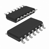
HEF4013BT,653 NXP Semiconductors, HEF4013BT,653 Datasheet - Page 2

HEF4013BT,653
Manufacturer Part Number
HEF4013BT,653
Description
IC FLIP FLOP DUAL DTYPE 14SOIC
Manufacturer
NXP Semiconductors
Series
4000Br
Type
D-Typer
Specifications of HEF4013BT,653
Package / Case
14-SOIC (3.9mm Width), 14-SOL
Function
Set(Preset) and Reset
Output Type
Differential
Number Of Elements
2
Number Of Bits Per Element
1
Frequency - Clock
40MHz
Trigger Type
Positive Edge
Current - Output High, Low
3.4mA, 3.4mA
Voltage - Supply
3 V ~ 15 V
Operating Temperature
-40°C ~ 125°C
Mounting Type
Surface Mount
Number Of Circuits
2
Logic Family
HEF4000
Logic Type
D-Type Edge Triggered Flip-Flop
Polarity
Inverting/Non-Inverting
Input Type
Single-Ended
Propagation Delay Time
30 ns at 15 V
High Level Output Current
- 4.2 mA
Low Level Output Current
4.2 mA
Supply Voltage (max)
15.5 V
Maximum Operating Temperature
+ 125 C
Mounting Style
SMD/SMT
Minimum Operating Temperature
- 40 C
Supply Voltage (min)
4.5 V
Lead Free Status / RoHS Status
Lead free / RoHS Compliant
Delay Time - Propagation
-
Lead Free Status / Rohs Status
Lead free / RoHS Compliant
Other names
933372660653
HEF4013BTD-T
HEF4013BTD-T
HEF4013BTD-T
HEF4013BTD-T
Available stocks
Company
Part Number
Manufacturer
Quantity
Price
Part Number:
HEF4013BT,653
Manufacturer:
NEXPERIA/安世
Quantity:
20 000
Philips Semiconductors
INTRODUCTION
These specifications cover the common electrical characteristics of the entire HE4000B family, unless otherwise
specified in the individual device data sheet.
The LOCMOS HE4000B family devices will operate over a recommended V
referenced to V
operating voltage, power supply regulation is less critical than with other types of logic. The lower limit of the supply
voltage is 3 V, or as determined by required system speed and/or noise immunity or interface to other logic. The
recommended upper limit is 15 V or as determined by power dissipation constraints or interface to other logic. Unused
inputs must be connected to V
a wide variety of device-handling situations. However, to be totally safe, it is desirable to take handling precautions into
account.
RATINGS
Limiting values in accordance with the Absolute Maximum System (IEC 134)
January 1995
V
V
P
P
T
T
T
SYMBOL
I
stg
amb
amb
DD
I
tot
Supply voltage
Voltage on any input
DC current into any input or output
Power dissipation per package
Power dissipation per output
Storage temperature
Operating ambient temperature (HEF)
Operating ambient temperature (HEC)
HEF (plastic and ceramic DIL)
HEF (plastic SO mini-pack)
HEC (ceramic DIL)
SS
(usually ground). Parametric limits are guaranteed for V
PARAMETER
DD
, V
SS
or another input. Inputs and outputs are protected against electrostatic effects in
T
T
T
T
T
T
amb
amb
amb
amb
amb
amb
CONDITIONS
= 40 to +70 C
= +70 to +85 C
= 40 to +70 C
= +70 to +85 C
= 55 to +70 C
= +70 to +125 C
2
DD
DD
of 5, 10 and 15 V. Because of the wide
power supply range of 3 to 15 V, as
derate linearly with 12 mW/K
derate linearly with 8 mW/K
derate linearly with 8 mW/K
0.5
0.5
65
40
55
MIN.
Family Specifications
TYP.
+18
V
10
750
500
500
100
+150
+85
+125
DD
MAX.
+ 0.5 V
V
mA
mW
mW
mW
mW
UNIT
C
C
C


