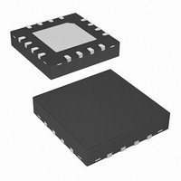
ISL9205IRZ-T Intersil, ISL9205IRZ-T Datasheet - Page 4

ISL9205IRZ-T
Manufacturer Part Number
ISL9205IRZ-T
Description
IC CHRGR LI-ION SGL 4.2V 16-QFN
Manufacturer
Intersil
Datasheet
1.ISL9205CIRZ.pdf
(14 pages)
Specifications of ISL9205IRZ-T
Function
Charge Management
Battery Type
Lithium-Ion (Li-Ion), Lithium-Polymer (Li-Pol)
Voltage - Supply
4.25 V ~ 6.5 V
Operating Temperature
-40°C ~ 85°C
Mounting Type
Surface Mount
Package / Case
16-VQFN Exposed Pad, 16-HVQFN, 16-SQFN, 16-DHVQFN
Lead Free Status / RoHS Status
Lead free / RoHS Compliant
Pin Description
VIN (Pin 1, 15, 16 for ISL9205; Pin 1 for ISL9205A,
ISL9205B, ISL9205C and ISL9205D)
VIN is the input power source. Connect to a wall adapter.
FAULT (Pin 2)
FAULT is an open-drain output indicating fault status. This
pin is pulled to LOW under any fault condition. When a fault
condition occurs, the time counter will be reset. When the
charger is disabled, the FAULT pin outputs high impedance.
STATUS (Pin 3)
STATUS is an open-drain output indicating charging and
inhibit states. The STATUS pin is pulled LOW when the
charger is charging a battery. It will be turned into high
impedance when the charge current drops to IMIN. This high
impedance state will be latched until a recharge cycle or a
new charge cycle starts. When the charger is disabled, the
STATUS pin outputs high impedance.
TIME (Pin 4)
The TIME pin determines the oscillation period by
connecting a timing capacitor between this pin and GND.
The oscillator also provides a time reference for the charger.
GND (Pin 5)
GND is the connection to system ground.
TOEN (Pin 6 for ISL9205; N/A for ISL9205A,
ISL9205B, ISL9205C and ISL9205D)
TOEN is the TIMEOUT enable input pin. Pulling this pin to
LOW disables the TIMEOUT charge-time limit for the fast
charge modes. Leaving this pin HIGH or floating enables the
TIMEOUT limit. There is an internal 400kΩ pull-up resistor at
this pin.
EN (Pin 7 for ISL9205; Pin 6 for ISL9205A,
ISL9205B, ISL9205C and ISL9205D)
EN is the enable logic input. Connect the EN pin to LOW to
disable the charger or leave it floating to enable the charger.
There is an internal 400kΩ pull-up resistor at this pin.
4
ISL9205
V2P8 (Pin 8 for ISL9205; Pin 7 for ISL9205A,
ISL9205B, ISL9205C and ISL9205D)
This is a 2.8V reference voltage output. This pin provides a
2.8V voltage source when the input voltage is above the
POR threshold and outputs zero otherwise. The V2P8 pin
can be used as an indication for adapter presence.
IREF (Pin 9 for ISL9205; Pin 8 for ISL9205A,
ISL9205B, ISL9205C and ISL9205D)
This is the charge current programming and monitoring pin.
Connect a resistor between this pin and GND to set the
charge current during the constant current phase, as given
by Equation 1:
Where R
IMIN (Pin 10 for ISL9205; N/A for ISL9205A,
ISL9205B, ISL9205C and ISL9205D)
IMIN is the end-of-charge (EOC) current programming pin.
Connect a resistor between this pin and GND to set the EOC
current, as given by Equation 2:
Where R
TEMP (Pin 11 for ISL9205; Pin 9 for ISL9205D; N/A
for ISL9205A, ISL9205B and ISL9205C)
TEMP is the input for an external NTC thermistor. The TEMP
pin is also used for battery removal detection.
VSEN (Pin 12 ISL9205; Pin 9 for ISL9205A,
ISL9205B and ISL9205; N/A for ISL9205D)
VSEN is the remote voltage sense pin. Connect this pin as
close to the battery positive terminal as possible. If the
VSEN pin is left floating, its voltage drops to zero volt and the
charger operates in trickle mode.
VBAT (Pin 13, 14 for ISL9205; Pin 10 for ISL9205A,
ISL9205B, ISL9205C and ISL9205D)
VBAT is the connection to the battery. Typically a 10μF
Tantalum capacitor is needed for stability when there is no
battery attached. When a battery is attached, only a 0.1μF
ceramic capacitor is required.
I
I
REF
MIN
=
=
----------------
R
---------------- -
R
8000
IREF
IMIN
IMIN
IREF
80
is in kΩ.
is in kΩ.
(
( )
mA
A
)
July 28, 2010
FN9252.2
(EQ. 1)
(EQ. 2)


