ISL6253HAZ-T Intersil, ISL6253HAZ-T Datasheet - Page 18
ISL6253HAZ-T
Manufacturer Part Number
ISL6253HAZ-T
Description
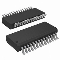
IC BATTERY CHRGR NOTEBOOK 28QSOP
Manufacturer
Intersil
Datasheet
1.ISL6253HAZ.pdf
(22 pages)
Specifications of ISL6253HAZ-T
Function
Charge Management
Battery Type
Lithium-Ion (Li-Ion), Lithium-Polymer (Li-Pol)
Voltage - Supply
7 V ~ 25 V
Operating Temperature
-10°C ~ 100°C
Mounting Type
Surface Mount
Package / Case
28-SSOP (0.150", 3.95mm Width)
Lead Free Status / RoHS Status
Lead free / RoHS Compliant
Available stocks
Company
Part Number
Manufacturer
Quantity
Price
Company:

Part Number:
ISL6253HAZ-T
Manufacturer:
Intersil
Quantity:
1 600


PWM Comparator Gain F
The PWM comparator gain Fm for peak current mode
control is given by:
where V
signal.
Current Sampling Transfer Function H
In current loop, the current signal is sampled every switching
cycle. It has the following transfer function:
where Q
respectively.
Power Stage Transfer Functions
Transfer function F
Where
Transfer function F
Current loop gain T
equation:
where R
usually equal to the product of the current sensing resistance
of the current amplifier. For ISL6253, R
The voltage gain with open current loop is:
where
error amplifier.
The Voltage loop gain with current loop closed is given by:
F
H
F
T
T
F
L
m
2
i
v
1
e
v
( )
( )
( )
( )
( )
S
( )
S
S
S
S
S
=
=
---------------- -
v ˆ
=
=
=
=
=
K
comp
R
PWM
ω
i ˆ
--- -
T
n
d ˆ
d ˆ
o
KF
v ˆ
----- -
T
S
------ -
ω
----------------------- -
1
d ˆ
=
esr
is the trans-resistance in current loop. R
and ω
o
=
F
2
2
n
T
+
m
m
V
---------- -
v
+
=
-------------------- -
R
V
T
=
( )
=
F
F
FB
S
i
is the peak-peak voltage of the PWM ramp
-------------- -
ω
o
o
V
( )
V
1
2
-------------- -
R
S
-----------------
V
n
+
( )A
S
in
in
( )H
, V
n
Q
c
S
S
PWM
1
R
-------------------------------------- -
C
S
------ -
ω
1
are given by
n
L
FB
1
2
2
2
o
o
i
+
(S) is expressed as the following
(S) from control to output voltage is:
,
(S) from control to inductor current is,
1
v
e
+
-------------------------------------- - where
S
------ -
ω
Q
1
( )
( )
is the feedback voltage of the voltage
+
S
-------------- -
ω
2
2
o
S
p
----------- -
ω
o
+
S
≈
1
Q
S
esr
-------------- -
ω
R
+
p
o
o
S
------
ω
+
Q
S
18
z
m
1
p
C
------ - ω
L
+
o
Q
,
1
n
=
o
–
=
2
-- -
π
-------------- -
T
,
LC
ω
1
= 24R
n
ω
o
=
z
≈
πf
e
-------------- -
R
s
(S)
1
o
.
,
1
C
T
o
(EQ. 24)
(EQ. 18)
is
(EQ. 19)
(EQ. 20)
(EQ. 23)
(EQ. 21)
(EQ. 22)
ISL6253
If T
follows:
Where RTV is the trans-resistance due to the current
information fed into the voltage loop. From the above
equation, it is shown that the system is a single order
system, which has a single pole located at
half switching frequency. Therefore, a simple type II
compensator can be easily used to stabilize the system.
Figure 20 shows the type II compensator, and its transfer
function is expressed as follows:
L
v
+
FIGURE 19. SMALL SIGNAL MODEL OF SYNCHRONOUS
( )
i
(S)>>1, then the above equation can be simplified as
S
v
^
i
^
in
in
=
V
---------- -
V
FB
o
I
L
FIGURE 20. TYPE II COMPENSATOR
R
-------------------- -
d ^
Fm
BUCK REGULATOR
o
R
+
Vo
Vo
+
TV
1:D
d
^
R
V
V
V
V
REF
REF
FB
FB
L
1
--------------------- -
1
+
V
+
-
-
+
+
----------- -
ω
in
He(S)
+
------ -
ω
S
S
d
esr
g
g
^
p
m
m
^
i
A
---------------- ω
H
L
T
v
e
i
( )
(S)
( )
S
V
S
C1
C1
R1
R1
^
L
comp
V
V
,
COMP
COMP
p
R
≈
T
-Av(S)
C2
C2
-------------- -
R
o
1
C
ω
o
p
Rc
Co
before the
T
Ro
v
(S)
(EQ. 25)
V
^
o
K
Related parts for ISL6253HAZ-T
Image
Part Number
Description
Manufacturer
Datasheet
Request
R

Part Number:
Description:
Highly Integrated Battery Charger
Manufacturer:
Intersil Corporation
Datasheet:
Part Number:
Description:
Intersil Corporation [CMOS Serial Controller Interface]
Manufacturer:
Intersil Corporation
Datasheet:
Part Number:
Description:
Manufacturer:
Intersil Corporation
Datasheet:
Part Number:
Description:
357-036-542-201 CARDEDGE 36POS DL .156 BLK LOPRO
Manufacturer:
Intersil Corporation
Datasheet:
Part Number:
Description:
1024-Word x 4-Bit LSI Static RAM
Manufacturer:
Intersil Corporation
Datasheet:
Part Number:
Description:
General Purpose NPN Transistor Arrays FN341.4
Manufacturer:
Intersil Corporation
Datasheet:
Part Number:
Description:
CMOS 16-Bit Microprocessor
Manufacturer:
Intersil Corporation
Datasheet:
Part Number:
Description:
Manufacturer:
Intersil Corporation
Datasheet:
Part Number:
Description:
Manufacturer:
Intersil Corporation
Datasheet:
Part Number:
Description:
Manufacturer:
Intersil Corporation
Datasheet:
Part Number:
Description:
Manufacturer:
Intersil Corporation
Datasheet:
Part Number:
Description:
CMOS 6-Bit Latch and Decoder Memory Interfaces
Manufacturer:
Intersil Corporation
Datasheet:
Part Number:
Description:
CA3046General Purpose NPN Transistor Arrays
Manufacturer:
Intersil Corporation
Datasheet:
Part Number:
Description:
Manufacturer:
Intersil Corporation
Datasheet:
Part Number:
Description:
TR909 DLC/FLC SLIC with Low Power Standby
Manufacturer:
Intersil Corporation
Datasheet: