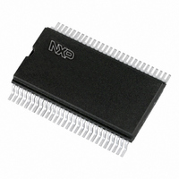
PCF8576T,118 NXP Semiconductors, PCF8576T,118 Datasheet - Page 8

PCF8576T,118
Manufacturer Part Number
PCF8576T,118
Description
IC LCD DVR UNVRSL LOW-MUX 56VSO
Manufacturer
NXP Semiconductors
Datasheet
1.PCF8576DT2118.pdf
(50 pages)
Specifications of PCF8576T,118
Display Type
LCD
Configuration
40 Segment
Interface
I²C
Current - Supply
180µA
Voltage - Supply
2 V ~ 9 V
Operating Temperature
-40°C ~ 85°C
Mounting Type
Surface Mount
Package / Case
56-VSOP
Lead Free Status / RoHS Status
Lead free / RoHS Compliant
Digits Or Characters
-
Other names
933740730118
PCF8576TD-T
PCF8576TD-T
PCF8576TD-T
PCF8576TD-T
NXP Semiconductors
PCF8576D
Product data sheet
7.2 LCD bias generator
7.3 LCD voltage selector
Data transfers on the I
reset action to complete.
Fractional LCD biasing voltages are obtained from an internal voltage divider consisting of
three impedances connected in series between V
bypassed to provide a
voltage can be temperature compensated externally using the supply to pin V
The LCD voltage selector coordinates the multiplexing of the LCD in accordance with the
selected LCD drive configuration. The operation of the voltage selector is controlled by the
mode-set command (see
that apply to the preferred modes of operation, together with the biasing characteristics as
functions of V
Table 5.
A practical value for V
threshold voltage (V
the static drive mode a suitable choice is V
Multiplex drive modes of 1:3 and 1:4 with
hence the contrast ratios are smaller.
Bias is calculated by
The RMS on-state voltage (V
V
LCD drive
mode
static
1:2 multiplex 2
1:2 multiplex 2
1:3 multiplex 3
1:4 multiplex 4
•
•
•
•
on RMS
a = 1 for
a = 2 for
(
Input and output bank selectors are reset
The I
The data pointer and the subaddress counter are cleared (set to logic 0)
Display is disabled
)
2
=
C-bus interface is initialized
Discrimination ratios
1
1
⁄
⁄
V
2
3
LCD
LCD
Number of:
Backplanes Levels
1
bias
bias
All information provided in this document is subject to legal disclaimers.
----------------------------- -
n
a
and the resulting discrimination ratios (D), are given in
2
×
th
+
(
------------ -
1
), typically when the LCD exhibits approximately 10 % contrast. In
1
Rev. 10 — 14 February 2011
LCD
2a
2
1
C-bus must be avoided for 1 ms following power-on to allow the
1
+
+
⁄
2
a
+
a
bias voltage level for the 1:2 multiplex configuration. The LCD
Table
is determined by equating V
)
, where the values for a are
n
2
3
4
4
4
2
on(RMS)
9) from the command decoder. The biasing configurations
LCD bias
configuration
static
1
1
1
1
⁄
⁄
⁄
⁄
) for the LCD is calculated with
2
3
3
3
1
Universal LCD driver for low multiplex rates
⁄
LCD
2
bias are possible but the discrimination and
> 3V
LCD
th
0
0.354
0.333
0.333
0.333
V
------------------------ -
.
and V
off RMS
V
off(RMS)
LCD
(
SS
)
. The middle resistor can be
with a defined LCD
1
0.791
0.745
0.638
0.577
V
----------------------- -
on RMS
V
(
LCD
PCF8576D
Equation 1
)
© NXP B.V. 2011. All rights reserved.
Table
∞
2.236
2.236
1.915
1.732
D
=
LCD
5.
------------------------ -
V
V
off RMS
on RMS
.
(
(
8 of 50
)
(1)
)


