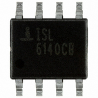
ISL6140CB Intersil, ISL6140CB Datasheet

ISL6140CB
Specifications of ISL6140CB
Available stocks
Related parts for ISL6140CB
ISL6140CB Summary of contents
Page 1
... CAUTION: These devices are sensitive to electrostatic discharge; follow proper IC Handling Procedures. | 1-888-INTERSIL or 1-888-468-3774 Intersil (and design registered trademark of Intersil Americas Inc. Copyright Intersil Americas Inc. 2001, 2003, 2004, 2010. All Rights Reserved All other trademarks mentioned are the property of their respective owners 100µF (100V) ...
Page 2
... ISL6140 has active Low (L version) PWRGD output pin ISL6150 has active High (H version) PWRGD output pin Ordering Information PART NUMBER (Notes 2, 3) PART MARKING ISL6140CBZ ISL61 40CBZ ISL6140CBZ-T (Note 1) ISL61 40CBZ ISL6140IBZ-T (Note 1) ISL61 40IBZ ISL6140IBZ ISL61 40IBZ ISL6150CB ISL 6150CB ISL6150CBZ ...
Page 3
Note that for both versions, although this is a digital pin functionally, the logic high level is determined by the external pull-up device, and the power supply to which it is connected; the IC will not clamp it below the ...
Page 4
... Thermal Resistance (Typical, Note 4) 8 Lead SOIC . . . . . . . . . . . . . . . . . . . . . . . Maximum Junction Temperature (Plastic Package +150°C Maximum Storage Temperature Range . . . -65°C to +150°C Pb-Free Reflow Profile . . . . . . . . . . . . . . . . . .see link below http://www.intersil.com/pbfree/Pb-FreeReflow.asp = +48V, VEE = +0V Unless Otherwise Specified. All tests are over the full temperature DD TEST SYMBOL ...
Page 5
Electrical Specifications V range; either Commercial (0°C to +70°C) or Industrial (-40°C to +85°C). Typical specs are at +25°C. Boldface limits apply over the operating temperature range, -40°C to +85°C. (Continued) PARAMETER DRAIN PIN Power Good Threshold ( ...
Page 6
Test Circuit and Timing Diagrams PWRGD ISL6140 ISL6150 FIGURE 1. TYPICAL TEST CIRCUIT 2V 1.223V PHLOV 13V GATE 1V 0V FIGURE ...
Page 7
ISL6140/ISL6150 Block Diagram GND UVL OVH + (1.223V -48V Typical Values ...
Page 8
be selected based on several criteria: maximum voltage expected on the input supply (including transients) as well as transients on the output side; maximum current expected; power dissipation and/or safe-operating-area considerations (due to the quick overcurrent latch, power dissipation is ...
Page 9
Applications: Overcurrent CORRECT INCORRECT TO SENSE AND V EE CURRENT SENSE RESISTOR FIGURE 5. SENSE RESISTOR Physical layout of R resistor is critical to avoid 1 SENSE the possibility of false overcurrent occurrences. Since the main input-to-output ...
Page 10
The three resistors ( the recommended approach for most cases. But if acceptable values can’t be found, then consider 2 separate resistor ...
Page 11
ISL6150 (H version; Figure 9): Under normal conditions (DRAIN < VPG), the Q 3 shorting the bottom of the internal resistor to V turning Q off. If the pull-up current from the external 2 module is high enough, the voltage ...
Page 12
The Enable input often has a pull-up resistor or current source, or equivalent built in; care must be taken in the ISL6150 (H version) output that the given current will create a high enough input voltage (remember that current through ...
Page 13
Typical Performance Curves 1.0 0.8 0.6 0.4 0.2 0 VOLTAGE (V) DD FIGURE 10 1.0 0.8 0.6 0.4 0.2 0 VOLTAGE (V) DD FIGURE 12. ...
Page 14
Typical Performance Curves 14.5 14.0 13.5 13.0 12.5 12.0 -40 10 TEMPERATURE (°C) FIGURE 16. GATE VOLTAGE (AT V -0.048 -0.050 -0.052 -0.054 -0.056 -0.058 -40 10 TEMPERATURE (°C) FIGURE 18. GATE PULL-UP CURRENT 0.34 0.32 0.30 0.28 0.26 0.24 ...
Page 15
Typical Performance Curves 1.90 1.85 1.80 1.75 1.70 1.65 -40 10 TEMPERATURE (°C) FIGURE 22. DRAIN/PG UP TRIP VOLTAGE 0.55 0.53 0.51 0.49 0.47 0.45 -40 10 TEMPERATURE (°C) FIGURE 24. DRAIN/PG HYSTERESIS VOLTAGE 15 ISL6140, ISL6150 (Continued) 1.35 1.30 ...
Page 16
Inrush Current In the example in Figure 26, the supply voltage is 48V and the load resistor (RL) is 620Ω, for around 80mA. The load capacitance is 100μF (100V). The Sense Resistor ( 0.02Ω (trip point at 2.5A; ...
Page 17
GND GND R 11 (SHORT PIN) SW1 G NFET* (INSTEAD SW1 FIGURE 29. ISL6140/50 OPTIONAL COMPONENTS (SHOWN WITH *) Optional Components voltage suppressor; SMAT70A or equivalent. ...
Page 18
GND -48V IN . GND ISL6140 SENSE GATE ...
Page 19
... Accordingly, the reader is cautioned to verify that data sheets are current before placing orders. Information furnished by Intersil is believed to be accurate and reliable. However, no responsibility is assumed by Intersil or its subsidiaries for its use; nor for any infringements of patents or other rights of third parties which may result from its use. No license is granted by implication or otherwise under any patent or patent rights of Intersil or its subsidiaries ...


