LP5521TM/NOPB National Semiconductor, LP5521TM/NOPB Datasheet - Page 19
LP5521TM/NOPB
Manufacturer Part Number
LP5521TM/NOPB
Description
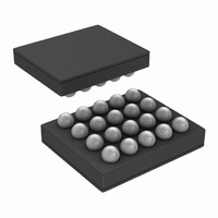
IC LED DRIVER RGB 25-USMD
Manufacturer
National Semiconductor
Series
PowerWise®r
Type
RGB LED Driverr
Datasheet
1.LP5521TMNOPB.pdf
(40 pages)
Specifications of LP5521TM/NOPB
Constant Current
Yes
Topology
PWM, Switched Capacitor (Charge Pump)
Number Of Outputs
3
Internal Driver
Yes
Type - Primary
Backlight, Light Management Unit (LMU)
Type - Secondary
RGB
Frequency
1.25MHz
Voltage - Supply
2.7 V ~ 5.5 V
Voltage - Output
4.55V
Mounting Type
Surface Mount
Package / Case
20-MicroSMD
Operating Temperature
-30°C ~ 85°C
Current - Output / Channel
25.5mA
Internal Switch(s)
Yes
Efficiency
95%
Lead Free Status / RoHS Status
Lead free / RoHS Compliant
Other names
LP5521TMTR
Available stocks
Company
Part Number
Manufacturer
Quantity
Price

Part Number:
LP5521TM/NOPB
Manufacturer:
NS/国半
Quantity:
20 000


LED Controller Programming Commands
LP5521 has three independent programmable channels (R,
G, B). Trigger connections between channels are common for
all channels. All channels have own program memories for
storing complex patterns. Brightness control and patterns are
done with 8-bit PWM control (256 steps) to get accurate and
smooth color control.
Program execution is timed with 32 768 Hz clock. This clock
can be generated internally or external 32 kHz clock can be
connected to CLK_32K pin. Using external clock enables
synchronization of LED timing to this clock rather than internal
X means do not care whether 1 or 0.
Ramp/Wait
Ramp command generates a PWM ramp starting from current
value. At each ramp step the output is incremented by one.
Time for one step is defined with Prescale and Step time bits.
Minimum time for one step is 0.49 ms and maximum time is
63 x 15.6 ms = 1 second/step, so it is possible to program very
fast and also very slow ramps. Increment value defines how
many steps are taken in one command. Number of actual
steps is Increment + 1. Maximum value is 127d, which corre-
sponds to half of full scale (128 steps). If during ramp com-
mand PWM reaches minimum/maximum (0/255) ramp com-
mand will be executed to the end and PWM will stay at
Go to Start
Ramp/Wait command
Command
Set PWM
Branch
Trigger
15
Ramp
0
Wait
End
Increment
Step time
Prescale
scale
Name
Pre-
Sign
14
15
0
0
0
1
1
1
13
scale
Pre-
14
1
0
0
1
1
12
13
1
0
1
Value(d)
11
Step time
0-127
1-63
12
Int
0
1
0
1
Wait for trigger on channels 5-0
Reset
10
11
Step time
0
0
Loop count
10
9
One ramp increment done in (step time) x (clock after prescale) Note: 0
Divides master clock (32 768Hz) by 16 = 2048 Hz, 0.49 ms cycle time
Divides master clock (32 768Hz) by 512 = 64 Hz, 15.6 ms cycle time
The number of steps is Increment + 1. Note: 0 is a wait instruction.
9
8
19
Sign
8
7
clock. Selection of the clock is made with address 08H bits
INT_CLK_EN and CLK_DET_EN. See External Clock Detec-
tion for details.
Supported commands are listed in the table below. Com-
mand compiler is available for easy sequence program-
ming. With Command compiler it is possible to write
sequences with simple ASCII commands, which are then
converted to binary or hex format. See application note
"LP5521 Programming Considerations" for examples of
Command compiler usage.
minimum/maximum. This enables ramp command to be used
as combined ramp and wait command in a single instruction.
Ramp command can be used as wait instruction when incre-
ment is zero.
Setting register 00H bit LOG_EN sets the scale from linear to
logarithmic. When LOG_EN = 0 linear scale is used, and
when LOG_EN = 1 logarithmic scale is used. By using loga-
rithmic scale the visual effect of the ramp command seems
linear to the eye.
Sign
7
0
6
means Set PMW command.
Decrease PWM output
Increase PWM output
6
0
x
5
Description
Send trigger on channels 5-0
X
5
0
Increment (number of steps)
4
PWM Value
Step / command number
4
0
Increment
3
3
0
2
2
0
1
www.national.com
1
0
0
X
0
0
Related parts for LP5521TM/NOPB
Image
Part Number
Description
Manufacturer
Datasheet
Request
R

Part Number:
Description:
Programmable Three Channel LED Driver
Manufacturer:
NSC [National Semiconductor]
Datasheet:

Part Number:
Description:
National Semiconductor [8-Bit D/A Converter]
Manufacturer:
National Semiconductor
Datasheet:
Part Number:
Description:
National Semiconductor [Media Coprocessor]
Manufacturer:
National Semiconductor
Datasheet:
Part Number:
Description:
Digitally Controlled Tone and Volume Circuit with Stereo Audio Power Amplifier, Microphone Preamp Stage and National 3D Sound
Manufacturer:
National Semiconductor
Datasheet:
Part Number:
Description:
Digitally Controlled Tone and Volume Circuit with Stereo Audio Power Amplifier, Microphone Preamp Stage and National 3D Sound
Manufacturer:
National Semiconductor
Datasheet:
Part Number:
Description:
AC97 Rev 2 Codec with Sample Rate Conversion and National 3D Sound
Manufacturer:
National Semiconductor
Part Number:
Description:
Manufacturer:
National Semiconductor
Datasheet:
Part Number:
Description:
Manufacturer:
National Semiconductor
Datasheet:
Part Number:
Description:
General Purpose, Low Voltage, Low Power, Rail-to-Rail Output Operational Amplifiers
Manufacturer:
National Semiconductor
Datasheet:
Part Number:
Description:
8-bit 20 MSPS flash A/D converter.
Manufacturer:
National Semiconductor
Datasheet:
Part Number:
Description:
Low Noise Quad Operational Amplifier
Manufacturer:
National Semiconductor
Datasheet:
Part Number:
Description:
Quad Differential Line Receivers
Manufacturer:
National Semiconductor
Datasheet:
Part Number:
Description:
Quad High Speed Trapezoidal? Bus Transceiver
Manufacturer:
National Semiconductor
Datasheet:
Part Number:
Description:
Dual Line Receiver
Manufacturer:
National Semiconductor
Datasheet: