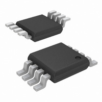
EL7513IY Intersil, EL7513IY Datasheet - Page 10

EL7513IY
Manufacturer Part Number
EL7513IY
Description
IC LED DRIVR WHITE BCKLGT 8-MSOP
Manufacturer
Intersil
Type
Backlight, White LEDr
Datasheet
1.EL7513IWTZ-T7A.pdf
(12 pages)
Specifications of EL7513IY
Constant Current
Yes
Topology
PWM, Step-Up (Boost)
Number Of Outputs
1
Internal Driver
Yes
Type - Primary
Backlight
Type - Secondary
White LED
Frequency
800kHz ~ 1.2MHz
Voltage - Supply
2.6 V ~ 13.2 V
Voltage - Output
18V
Mounting Type
Surface Mount
Package / Case
8-MSOP, Micro8™, 8-uMAX, 8-uSOP,
Operating Temperature
-40°C ~ 85°C
Current - Output / Channel
75mA
Internal Switch(s)
Yes
Efficiency
91%
Lead Free Status / RoHS Status
Contains lead / RoHS non-compliant
When choosing an inductor, make sure the inductor can
handle the average and peak currents giving by following
formulas (80% efficiency assumed):
where:
• ΔI
• L inductance in µH
• FS switching frequency, typical 1MHz
A wide range of inductance (6.8µH - 68µH) can be used for
the converter to function correctly. For the same series of
inductors, the lower inductance has lower DC resistance
(DCR), which has less conducting loss. But the ripple current
is bigger, which generates more RMS current loss. Figure 11
shows the efficiency of the demo board under different
inductance for a specific series of inductor. For optimal
efficiency in an application, it is a good exercise to check
several adjacent inductance values of your preferred series
of inductors.
For the same inductance, higher overall efficiency can be
obtained by using lower DCR inductor.
I
I
ΔI
LAVG
LPK
FIGURE 21. EFFICIENCY OF DIFFERENT INDUCTANCE
L
L
=
=
is the peak-to-peak inductor current ripple in Ampere
V
-------------------------------------------- -
=
I
IN
LAVG
L
----------------------- -
0.8 V
85
83
81
79
77
I
×
×
O
5
(
V
EFFICIENCY vs I
×
×
V
O
V
DIFFERENT L
(4 LEDs IN A SERIES)
+
V
O
IN
×
L = 33µH
O
IN
1
-- -
2
–
F
= 3.3V FOR
×
V
S
ΔI
IN
10
L
)
O
15
10
I
O
(mA)
L = 22µH
L = Coilcraft
LPO1704 SERIES
1mm HEIGHT
20
L = 10µH
L = 15µH
25
30
(EQ. 2)
(EQ. 3)
(EQ. 4)
EL7513
The diode should be Schottky type with minimum reverse
voltage of 20V. The diode's peak current is the same as
inductor's peak current, the average current is I
current is:
Ensure the diode's ratings exceed these current
requirements.
White LED Connections
One leg of LEDs connected in series will ensure the
uniformity of the brightness. 18V maximum voltage enables
4 LEDs can be placed in series.
However, placing LEDs into series/parallel connection can
give higher efficiency as shown in the efficiency curves. One
of the ways to ensure the brightness uniformity is to pre-
screen the LEDs.
PCB Layout Considerations
The layout is very important for the converter to function
properly. Power Ground ( ) and Signal Ground (
be separated to ensure the high pulse current in the power
ground does not interference with the sensitive signals
connected to Signal Ground. Both grounds should only be
connected at one point right at the chip. The heavy current
paths (V
be as short as possible.
The trace connected to the CS pin is most important. The
current sense resister R
When the trace is long, use a small filter capacitor close to
the CS pin.
The heat of the IC is mainly dissipated through the PGND
pin. Maximizing the copper area around the plane is
preferable. In addition, a solid ground plane is always helpful
for the EMI performance.
The demo board is a good example of layout based on the
principle. Please refer to the EL7513 Application Brief for the
layout.
I
DRMS
=
IN
-L-L
I
LAVG
X
pin-PGND, and V
×
I
O
1
should be very close to the pin
IN
-L-D-C
2
-PGND) should
December 22, 2008
O
, and RMS
) should
(EQ. 5)
FN7112.5


