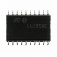
L6585DETR STMicroelectronics, L6585DETR Datasheet - Page 18

L6585DETR
Manufacturer Part Number
L6585DETR
Description
IC PFC/BALLAST CONTROL 20-SOIC
Manufacturer
STMicroelectronics
Type
PFC/Ballast Controllerr
Datasheet
1.L6585DETR.pdf
(33 pages)
Specifications of L6585DETR
Frequency
58.4 ~ 62 kHz
Current - Supply
7mA
Current - Output
600mA
Voltage - Supply
11 V ~ 16 V
Operating Temperature
-40°C ~ 150°C
Package / Case
20-SOIC (7.5mm Width)
Switching Frequency
250 KHz
Maximum Power Dissipation
830 mW
Maximum Operating Temperature
+ 150 C
Mounting Style
SMD/SMT
Minimum Operating Temperature
- 40 C
Lead Free Status / RoHS Status
Lead free / RoHS Compliant
Other names
497-8822-2
Available stocks
Company
Part Number
Manufacturer
Quantity
Price
Company:
Part Number:
L6585DETR
Manufacturer:
STMicroelectronics
Quantity:
1 792
Part Number:
L6585DETR
Manufacturer:
ST
Quantity:
20 000
Ballast section
6
6.1
6.2
18/33
Ballast section
Half-bridge drivers and integrated bootstrap diode
The half-bridge drivers are capable of 290 mA source and 480 mA sink current. This makes
them able to effectively drive also big MOSFETs Cg up to 2.2 nF. The high-side MOSFET is
driven by means of a bootstrapped structure reducing the number of external components.
Normal start-up description
Referring to
Figure 7.
1.
2.
Startup: As soon as Vcc reaches the startup threshold voltage references are built up,
the RF and EOLP pin are biased, the EOI pin is pulled down and the TCH pin starts
sourcing 31 µA. The frequency of the half-bridge is generated by an internal CCO,
connected to
pulled down, the startup frequency will be due to the current flowing in parallel with
R
Preheating: the TCH pin continues to source 31 µA until its voltage reaches 4.63 V,
therefore it is left in a high impedance status. As this pin loaded with an RC parallel
network, the voltage across this pin decreases exponentially. When it reaches 1.5 V the
TCH pin is pulled down and the preheating time ends. During this sequence the EOI
pin is pulled down and the half-bridge frequency is the startup frequency. A leading
PRE
and R
Figure
Normal start-up procedure
RUN
C
7, normal startup proceeds as follows:
OSC
(see typical application diagram).
and using the RF current as the control signal. With the EOI pin
L6585DE


