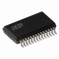
UBA2032TS/N2,118 NXP Semiconductors, UBA2032TS/N2,118 Datasheet - Page 12

UBA2032TS/N2,118
Manufacturer Part Number
UBA2032TS/N2,118
Description
IC DRIVER FULL BRIDGE 28-SSOP
Manufacturer
NXP Semiconductors
Datasheet
1.UBA2032TSN3118.pdf
(21 pages)
Specifications of UBA2032TS/N2,118
Configuration
H Bridge
Input Type
Self Oscillating
Current - Peak
130mA
Number Of Configurations
1
Number Of Outputs
4
High Side Voltage - Max (bootstrap)
550V
Voltage - Supply
10.5 V ~ 13.5 V
Operating Temperature
-40°C ~ 150°C
Mounting Type
Surface Mount
Package / Case
28-SSOP
Lead Free Status / RoHS Status
Lead free / RoHS Compliant
Delay Time
-
Other names
935270517118
UBA2032TSDB-T
UBA2032TSDB-T
UBA2032TSDB-T
UBA2032TSDB-T
Philips Semiconductors
APPLICATION INFORMATION
Basic application
A basic full bridge configuration with an HID lamp is shown
in Fig.5. The bridge disable, the start-up delay and the
external drive functions are not used in this application.
The pins LVS, +LVS, EXTDR and BD are short-circuited
to SGND. The internal oscillator is used and to realise a
50% duty cycle the internal divider function has to be used
by connecting pin DD to pin SGND.
2005 Mar 24
handbook, full pagewidth
Full bridge driver IC
(1) See Section “Gate resistors”.
high voltage
550 V (max)
GND
C i
C 3
C osc
R osc
EXTDR
SGND
V DD
LVS
LVS
HV
SU
DD
BD
RC
1
2
3
5
7
8
9
10
11
12
UBA2032T
Fig.5 Basic configuration.
24
23
22
20
18
17
15
14
13
PGND
GHR
FSR
SHR
GLR
GLL
SHL
FSL
GHL
12
R >100
R >100
C 2
C 1
The IC is powered by the high voltage supply. Because
the internal oscillator is used, the bridge commutating
frequency is determined by the values of R
The bridge starts oscillating when the HV supply voltage
exceeds the level of release power drive (typically 12.5 V
on pin HV). If the supply voltage on pin HV drops below the
reset level of power drive (typically 10 V on pin HV), the
UBA2032 enters the start-up state.
(1)
(1)
HR
LR
MGU546
IGNITOR
HL
LL
Product specification
R >100
R >100
UBA2032
osc
(1)
(1)
and C
osc
.


