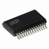
UBA2032TS/N2,118 NXP Semiconductors, UBA2032TS/N2,118 Datasheet - Page 15

UBA2032TS/N2,118
Manufacturer Part Number
UBA2032TS/N2,118
Description
IC DRIVER FULL BRIDGE 28-SSOP
Manufacturer
NXP Semiconductors
Datasheet
1.UBA2032TSN3118.pdf
(21 pages)
Specifications of UBA2032TS/N2,118
Configuration
H Bridge
Input Type
Self Oscillating
Current - Peak
130mA
Number Of Configurations
1
Number Of Outputs
4
High Side Voltage - Max (bootstrap)
550V
Voltage - Supply
10.5 V ~ 13.5 V
Operating Temperature
-40°C ~ 150°C
Mounting Type
Surface Mount
Package / Case
28-SSOP
Lead Free Status / RoHS Status
Lead free / RoHS Compliant
Delay Time
-
Other names
935270517118
UBA2032TSDB-T
UBA2032TSDB-T
UBA2032TSDB-T
UBA2032TSDB-T
Philips Semiconductors
Additional application information
G
At ignition of an HID lamp, a large EMC spark occurs. This
can result in a large voltage transient or oscillation at the
gates of the full bridge MOSFETs (LL, LR, HR and HL).
When these gates are directly coupled to the gate drivers
(pins GHR, GLR, GHL and GLL), voltage overstress of the
driver outputs may occur. Therefore, it is advised to add a
resistor with a minimum value of 100
gate driver to isolate the gate driver outputs from the actual
power MOSFETs gate.
It may be necessary to add a diode in parallel to these gate
resistors in order:
1. To switch off the power transistor in time
2. To ensure that the power transistor remains in off-state
2005 Mar 24
ATE RESISTORS
Full bridge driver IC
during a high V/ t at the bridge nodes; typical use
depends on the characteristics (gate charge, Miller
capacitance) of the power MOSFETs.
in series with each
15
G
USE
The total gate current needed to charge the gates of the
power MOSFETs equals:
Where:
This current is supplied via the internal low voltage supply
(V
Section “Characteristics”; table note 1), at higher
frequencies and with MOSFETs having a relative high
gate charge, this maximum V
sufficient anymore. As a result the internal low voltage
supply (V
in an increase of the on resistance (R
MOSFETs. In this case an auxiliary low voltage supply is
necessary.
I
gate
ATE CHARGE AND SUPPLY CURRENT AT HIGH FREQUENCY
I
f
Q
DD
gate
bridge
gate
). Since this current is limited to 11 mA (see
=
= gate current
= gate charge.
4 f
= bridge frequency
DD
) and the gate drive voltage will drop resulting
bridge
Q
gate
.
DD
supply current may not be
Product specification
on
) of the full bridge
UBA2032


