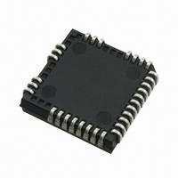
IRS26302DJPBF International Rectifier, IRS26302DJPBF Datasheet - Page 23

IRS26302DJPBF
Manufacturer Part Number
IRS26302DJPBF
Description
IC BRIDGE +1 GATE DVR 3PH 44PLCC
Manufacturer
International Rectifier
Datasheet
1.IRS26302DJTRPBF.pdf
(51 pages)
Specifications of IRS26302DJPBF
Configuration
3 Phase Bridge
Input Type
Non-Inverting
Delay Time
320ns
Current - Peak
200mA
Number Of Configurations
1
Number Of Outputs
3
High Side Voltage - Max (bootstrap)
600V
Voltage - Supply
10 V ~ 20 V
Operating Temperature
-40°C ~ 125°C
Mounting Type
Surface Mount
Package / Case
44-PLCC (32 Leads)
Number Of Drivers
6
Driver Configuration
Non-Inverting
Driver Type
High and Low Side
Input Logic Level
CMOS/TTL
Rise Time
190ns
Fall Time
75ns
Propagation Delay Time
710ns
Peak Output Current
350mA
Power Dissipation
4.6W
Operating Supply Voltage (min)
10V
Turn Off Delay Time
50ns
Turn On Delay Time (max)
50ns
Operating Temp Range
-40C to 125C
Operating Temperature Classification
Automotive
Mounting
Surface Mount
Pin Count
32
Package Type
PLCC
Lead Free Status / RoHS Status
Lead free / RoHS Compliant
Available stocks
Company
Part Number
Manufacturer
Quantity
Price
Company:
Part Number:
IRS26302DJPBF
Manufacturer:
International Rectifier
Quantity:
10 000
IRS26302DJ
The length of the fault clear time period can be determined by using the formula below.
-t/RC
(t) = V
(1-e
)
v
C
f
t
= -(R
C
)ln(1-V
/V
)
FLTCLR
RCIN
RCIN
RCIN,TH
CC
Over-Current Protections
The IRS26302DJ HVICs are equipped with an ITRIP, GF and PFCtrip input pin. These functionality can be used to
detect over-current events in the DC- bus, in the DC+ bus, in the PFC section and Ground related. Once the HVIC
detects an over-current event, the outputs are shutdown, a fault is reported through the FAULT pin, and RCIN is
pulled to V
.
SS
The level of current at which the over-current protection is initiated is determined by the resistor network (i.e., R
, R
,
0
1
and R
) connected to ITRIP as shown in Figure 14, and the ITRIP threshold (V
). The circuit designer will need to
2
IT,TH+
determine the maximum allowable level of current in the DC- bus and select R
, R
, and R
such that the voltage at
0
1
2
node V
reaches the over-current threshold (V
) at that current level.
X
IT,TH+
V
= R
I
(R
/(R
+R
))
IT,TH+
0
DC-
1
1
2
Figure 14: Programming the over-current protection
For example, a typical value for resistor R
could be 50 m . The voltage of the ITRIP pin should not be allowed to
0
exceed 5 V; if necessary, an external voltage clamp may be used.
The shunt resistor or resistor network for GF or PCFtrip can be determined according to GF, PCFtrip threshold and
level of protection current. The GF pin should not be outside this range (VDC+0.3V, VDC-5V) and PCFtrip should not
be outside (Vcc+0.3V, Vss-5V); if necessary, an external voltage clamp may be used.
Over-Temperature Shutdown Protection
The ITRIP input of the IRS26302DJ can also be used to detect over-temperature events in the system and initiate a
shutdown of the HVIC (and power switches) at that time. In order to use this functionality, the circuit designer will
need to design the resistor network as shown in Figure 15 and select the maximum allowable temperature.
This network consists of a thermistor and two standard resistors R
and R
. As the temperature changes, the
3
4
resistance of the thermistor will change; this will result in a change of voltage at node V
. The resistor values should
X
www.irf.com
© 2009 International Rectifier
23


