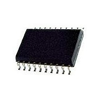
L6201PS STMicroelectronics, L6201PS Datasheet - Page 3

L6201PS
Manufacturer Part Number
L6201PS
Description
IC DRIVER FULL BRIDGE 20-PWRSOIC
Manufacturer
STMicroelectronics
Type
H Bridger
Datasheet
1.L6201013TR.pdf
(20 pages)
Specifications of L6201PS
Input Type
Non-Inverting
Number Of Outputs
2
On-state Resistance
300 mOhm
Current - Output / Channel
4A
Current - Peak Output
5A
Voltage - Supply
12 V ~ 48 V
Operating Temperature
-40°C ~ 150°C
Mounting Type
Surface Mount
Package / Case
PowerSO-20 Exposed Bottom Pad
Operating Supply Voltage
12 V to 48 V
Supply Current
0.015 A
Mounting Style
SMD/SMT
Motor Type
Full Bridge
No. Of Outputs
2
Output Current
5A
Output Voltage
60V
Supply Voltage Range
12V To 48V
Driver Case Style
SOIC
No. Of Pins
20
Operating Temperature Range
-40°C To +150°C
Rohs Compliant
Yes
Operating Current
15mA
Operating Temperature Classification
Automotive
Package Type
PowerSO
Operating Supply Voltage (min)
12V
Operating Supply Voltage (typ)
36V
Operating Supply Voltage (max)
48V
Lead Free Status / RoHS Status
Lead free / RoHS Compliant
Other names
497-1419-5
Available stocks
Company
Part Number
Manufacturer
Quantity
Price
Company:
Part Number:
L6201PS
Manufacturer:
STMicroelectronics
Quantity:
135
Part Number:
L6201PSTR
Manufacturer:
SOIC20
Quantity:
20 000
Company:
Part Number:
L6201PSTR-ST
Manufacturer:
ST
Quantity:
6
PINS FUNCTIONS
ABSOLUTE MAXIMUM RATINGS
Note 1: Pulse width limited only by junction temperature and transient thermal impedance (see thermal characteristics)
Note 2: Mounted on board with minimized dissipating copper area.
V
Symbol
L6201
T
14,15
16,17
V
IN
4,5
6,7
stg
V
10
11
12
13
18
19
20
P
sense
1
2
3
–
8
9
–
, V
V
V
I
OD
o
tot
, T
s
b
EN
j
L6201PS
2,3,9,12,
11, 20
18,19
1, 10
Power Supply
Differential Output Voltage (between Out1 and Out2)
Input or Enable Voltage
Pulsed Output Current
– Non Repetitive (< 1 ms) for L6201
DC Output Current
Sensing Voltage
Boostrap Peak Voltage
Total Power Dissipation:
T
T
T
Storage and Junction Temperature
16
17
13
14
15
pins
case
amb
–
–
–
4
5
6
7
8
–
–
Device
= 90 C for L6201
= 70 C for L6201 (Note 2)
= 90 C for L6201PS/L6203
L6202
10
11
12
13
14
15
16
17
18
1
2
3
4
5
6
7
8
9
for L6202
for L6202 (Note 2)
for L6201PS/L6203 (Note 2)
L6203
10
11
6
1
2
3
4
5
6
7
8
9
for L6201PS/L6202/L6203 (Note 1)
for L6201 (Note 1)
for L6201PS/L6202/L6203
Parameter
SENSE
ENAB
LE
N.C.
GND
GND
GND
N.C.
OUT2
V
OUT1
BOOT1
IN1
GND
GND
GND
IN2
BOOT2
V
Name
s
ref
A resistor R
motor current control.
When a logic high is present on this pin the DMOS POWER
transistors are enabled to be selectively driven by IN1 and IN2.
Not Connected
Common Ground Terminal
Common Ground Terminal
Common Ground Terminal
Not Connected
Ouput of 2nd Half Bridge
Supply Voltage
Output of first Half Bridge
A boostrap capacitor connected to this pin ensures efficient
driving of the upper POWER DMOS transistor.
Digital Input from the Motor Controller
Common Ground Terminal
Common Ground Terminal
Common Ground Terminal
Digital Input from the Motor Controller
A boostrap capacitor connected to this pin ensures efficient
driving of the upper POWER DMOS transistor.
Internal voltage reference. A capacitor from this pin to GND is
recommended. The internal Ref. Voltage can source out a
current of 2mA max.
sense
connected to this pin provides feedback for
Function
– 40 to + 150
– 0.3 to + 7
– 1 to + 4
L6201 - L6202 - L6203
Value
0.9
1.3
2.3
52
10
60
20
60
5
5
1
4
5
Unit
W
W
W
W
W
W
V
V
V
A
A
A
A
V
V
C
3/20


