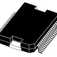
L9952XP STMicroelectronics, L9952XP Datasheet - Page 11

L9952XP
Manufacturer Part Number
L9952XP
Description
IC PWR MANAGEMENT SYST PWRSSO36
Manufacturer
STMicroelectronics
Datasheet
1.L9952GXPTR.pdf
(68 pages)
Specifications of L9952XP
Applications
Automotive
Voltage - Supply
6 V ~ 18 V
Operating Temperature
-40°C ~ 150°C
Mounting Type
Surface Mount
Package / Case
PowerSSO-36 Exposed Bottom Pad
Product
Fan / Motor Controllers / Drivers
Mounting Style
SMD/SMT
Lead Free Status / RoHS Status
Lead free / RoHS Compliant
Current - Supply
-
Lead Free Status / Rohs Status
Lead free / RoHS Compliant
Available stocks
Company
Part Number
Manufacturer
Quantity
Price
Company:
Part Number:
L9952XP
Manufacturer:
st
Quantity:
10 000
Part Number:
L9952XP
Manufacturer:
ST
Quantity:
20 000
Company:
Part Number:
L9952XPTR
Manufacturer:
st
Quantity:
10 000
Company:
Part Number:
L9952XPTR
Manufacturer:
MICREL
Quantity:
304
Part Number:
L9952XPTR
Manufacturer:
ST
Quantity:
20 000
L9952GXP
2
2.1
2.1.1
2.1.2
Description
Voltage regulator
The L9952GXP contains 2 independent and fully protected low drop voltage regulators,
which are designed for very fast transient response.
The output voltage is stable with loads capacitors > 220nF.
Voltage regulator: V1
The voltage regulator V1 provides 5V supply voltage and up to 250mA continuous load
current for the external digital logic (micro controller, CAN transceiver ...). In addition the
regulator V1 drives the L9952GXP internal 5V loads. The voltage regulator is protected
against overload and over-temperature. An external reverse current protection has to be
provided by the application circuitry to prevent the output capacitor from being discharged
by negative transients or low input voltage. The output voltage precision is better than +/-2%
(incl. temperature drift and line-/load regulation) for operating mode; respectively +/-3%
during low current mode. Current limitation of the regulator ensures fast charge of external
bypass capacitors. The output voltage is stable for ceramic load capacitors > 220nF.
If device Temperature exceeds TSD1 threshold, all outputs (Hsx, Lsx, V2, LIN) will be
deactivated except V1. Hence the micro controller has the possibility for interaction or error
logging. In case of exceeding TSD2 threshold (TSD2>TSD1), also V1 will be deactivated
(see state chart Fig. 3.1: “Protection and diagnosis”). A timer is started and the voltage
regulator is deactivated for t
LIN, and WU1...4) are disabled. After 1 sec, the voltage regulator will try to restart
automatically. If TSD2 occurs within one minute and for 8 consecutive times, the L9952GXP
enters the V
In case of short to GND at “V1” after initial turn on (V1 < 2V for at least 4ms) the L9952GXP
enters the V
signals from CAN, LIN, WU1..4, SPI.
Voltage regulator: V2
The voltage regulator V2 supplies additional 5V loads (e.g. Logic components, external
sensors, external potentiometers). The continuous load current is 50mA. The regulator
provides accuracy better than + 3% @ 50mA (4% @ 100mA) load current.
In case of short to GND at “V2” after initial turn on (V2 < 2V for at least 4ms) the V2
regulator is switched off. Micro processor has to send a clear command to reactivate the V2
regulator.
V2 is protected against:
●
●
●
●
Overload
Over temperature
Short circuit (short to ground and battery supply voltage)
Reverse biasing
BAT
BAT
- standby mode.
- standby mode. Reactivation (wake-up) of the device can be achieved with
TSD
Doc ID 13518 Rev 5
= 1sec. During this time, all other wakeup sources (CAN,
Description
11/68


