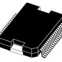
L9951 STMicroelectronics, L9951 Datasheet - Page 15

L9951
Manufacturer Part Number
L9951
Description
IC REAR DOOR ACT DVR POWERSO-36
Manufacturer
STMicroelectronics
Type
DC Motor Driverr
Datasheet
1.L9951XPTR.pdf
(36 pages)
Specifications of L9951
Applications
Automotive
Current - Supply
7mA
Voltage - Supply
7 V ~ 28 V
Operating Temperature
-40°C ~ 150°C
Mounting Type
Surface Mount
Package / Case
PowerSO-36 Exposed Bottom Pad
Operating Current
20mA
Operating Temperature Classification
Automotive
Motor Controller Type
DC Motor Driver
Package Type
PowerSO
Operating Supply Voltage (min)
7V
Operating Supply Voltage (max)
28V
Supply Current
20 mA
Mounting Style
SMD/SMT
Lead Free Status / RoHS Status
Lead free / RoHS Compliant
Available stocks
Company
Part Number
Manufacturer
Quantity
Price
Part Number:
L9951
Manufacturer:
ST
Quantity:
20 000
Part Number:
L9951XP
Manufacturer:
ST
Quantity:
20 000
Company:
Part Number:
L9951XPTR
Manufacturer:
st
Quantity:
6 966
Part Number:
L9951XPTR
Manufacturer:
ST
Quantity:
20 000
L9951 / L9951XP
Note:
Table 14.
1.
DI timing parameters tested in production by a passed/failed test:
Tj= -40°C/+25°C: SPI communication @2MHZ.
Tj= +125°C: SPI communication @1.25MHZ.
Table 15.
1. Value of input capacity is not measured in production test. Parameter guaranteed by design.
Table 16.
1. See
Symbol
Symbol
t
C
t
t
t
dis DO H tri
dis DO L tri
en DO tri H
Symbol
en DO tri L
V
I
V
DOLK
DO
t
t
See
DOH
t
r in
f in
DOL
t
t
d DO
r DO
f DO
(1)
Figure 5
Figure 3
Rise time of input signal DI,
CLK, CSN
Fall time of input signal DI,
CLK, CSN
Output low level
Output high level
Tristate leakage current
Tristate input capacitance
DI timing
DO
DO timing
DO rise time
DO fall time
DO enable time
from tristate to low level
DO disable time
from low level to tristate
DO enable time
from tristate to high level
DO disable time
from high level to tristate
DO delay time
and
and
Figure
Figure 4
Parameter
Parameter
Parameter
(1)
6.
(1)
(continued)
Doc ID 14173 Rev 8
C
C
C
pull-up load to V
C
pull-up load to V
C
pull-down load to GND
C
pull-down load to GND
V
C
DO
L
L
L
L
L
L
L
VCC = 5 V, I
VCC = 5 V, I
V
0V < V
V
0V < V
= 100 pF, I
= 100 pF, I
= 100 pF, I
= 100 pF, I
=100 pF, I
= 100 pF, I
= 100pF
CSN
CSN
< 0.3 V
Test condition
Test condition
Test condition
= V
= V
DO
CC
V
V
CC
CC
CC
CC
CC
< V
< 5.3V
load
load
load
load
load
load
, V
,
,
D
D
= 5V
= 5V
CC
CC
CC
= -1mA
= -4mA
= 4 mA
DO
= -1mA
= 1mA
= 1mA
= 4 mA
= -4mA
> 0.7V
CC
,
Min.
Min.
V
-0.4
-10
Electrical specifications
Min.
CC
Typ.
Typ.
V
-0.2
0.2
Typ.
10
100
380
100
380
80
50
50
CC
Max.
100
100
Max.
Max.
0.4
140
100
250
450
250
450
250
10
15
Unit
Unit
Unit
15/36
ns
ns
µA
pF
ns
ns
ns
ns
ns
ns
ns
V
V


