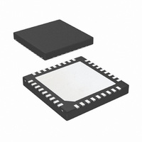
LP5551SQX/NOPB National Semiconductor, LP5551SQX/NOPB Datasheet - Page 28

LP5551SQX/NOPB
Manufacturer Part Number
LP5551SQX/NOPB
Description
IC ENERGY MGMNT SYSTEM 36-LLP
Manufacturer
National Semiconductor
Series
PowerWise®r
Datasheet
1.LP5551SQXNOPB.pdf
(32 pages)
Specifications of LP5551SQX/NOPB
Applications
Handheld/Mobile Devices
Current - Supply
431µA
Voltage - Supply
2.7 V ~ 5.5 V
Operating Temperature
-40°C ~ 85°C
Mounting Type
Surface Mount
Package / Case
36-LLP
For Use With
LP5551SQEV - BOARD EVALUATION LP5551SQ
Lead Free Status / RoHS Status
Lead free / RoHS Compliant
Other names
LP5551SQX
www.national.com
ripple current. Ceramic capacitors are predominately used in
portable systems and have very low ESR and remain capac-
itive up to high frequencies.
The switcher peak - to - peak output voltage ripple in steady
state can be calculated as:
LDO INFORMATION
The LDOs included in the LP5551 provide static supply volt-
ages for various functions in the processor. Use the following
sections to determine loading and external components.
1. LDO3 tracks the switching converter output voltage (V
2. LDO3 regulates at the set memory retention voltage when the LP5551 is in shutdown state.
LDO OUTPUT CAPACITOR
The output capacitor sets a low frequency pole and a high
frequency zero in the control loop of an LDO. The capacitance
and the equivalent series resistance (ESR) of the capacitor
must be within a specified range to meet stability require-
LDO1 R8
LDO2 R7
LDO3 R2
LDO4 R12
LDO1
LDO2
LDO3
LDO4
PWI Register Output voltage range Recommended Maximum
Output Capacitance Range (Recommended Typical Value)
1 µF – 20 µF (2.2 µF)
2 µF – 20 µF (4.7 µF)
0.7 µF – 2.2 µF (1.0 µF)
2 µF – 20 µF (4.7 µF)
0.6 V – 2.2 V
1.5 V – 3.3 V
V
0.7 V – 1.35 V
1.5 V – 3.3 V
OSW
+ 0.05 V
2
1
TABLE 2. Output Capacitor Selection Guide
Output Current
100 mA
250 mA
50 mA
250 mA
TABLE 1. LDO Parameters
OSW
) plus a 50 mV offset when the LP5551 is in active state.
28
LDO LOADING CAPABILITY
The LDOs in the LP5551 can regulate to a variety of output
voltages, depending on the need of the processor. These
voltages can be programmed through the PWI. Table 1 sum-
marizes the parameters of the LP5551 LDOs.
ments. The LDOs in the LP5551 are designed to be used with
ceramic output capacitors. The dielectric should be X5R,
X7R, or comparable material to maintain proper tolerances.
Use the following table to choose a suitable output capacitor:
Dropout Voltage
(typical)
200 mV
150 mV
200 mV
150 mV
ESR range
5 mohm – 500 mohm
5 mohm – 500 mohm
5 mohm– 500 mohm
5 mohm – 500 mohm
Typical Load
PLL
I/O
Memory/Memory
retention
User defined


