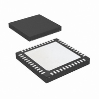
LP3913SQX-AC/NOPB National Semiconductor, LP3913SQX-AC/NOPB Datasheet - Page 37

LP3913SQX-AC/NOPB
Manufacturer Part Number
LP3913SQX-AC/NOPB
Description
IC PWR MANAGEMENT W/CHRGR 48-LLP
Manufacturer
National Semiconductor
Series
PowerWise®r
Datasheet
1.LP3913SQ-ACNOPB.pdf
(58 pages)
Specifications of LP3913SQX-AC/NOPB
Applications
Handheld/Mobile Devices
Voltage - Supply
2.5 V ~ 6 V
Operating Temperature
-40°C ~ 85°C
Mounting Type
Surface Mount
Package / Case
48-LLP
Lead Free Status / RoHS Status
Lead free / RoHS Compliant
Current - Supply
-
Other names
LP3913SQX-AC
Access
Data
Reset
Safety Timer
In order to prevent endless charging, which could degrade the
battery quality and life time, the LP3913 contains a safety
timer that limits charging regardless whether the battery has
reached its full capacity or not. In prequalification the safety
timer is 1 hour. In full rate or constant voltage charging the
safety timer is a maximum of 10 hours minus the time in pre-
qualification.
When the timer times out of uninterrupted charging, an IRQ
is generated to alert system processor. The status of the timer
can also be polled by reading the IRQ register if the system
doesn’t support hardware interrupts.
The Safety timer resets and starts counting from zero upon
the following events:
1.
2.
3.
4.
CHSPV Register (02)h Charger Supervisor Register
POWER ROUTING
The LP3913 power can originate from three different sources:
Adapter power, USB power or battery power. The objective
of the power routing is to be able to:
•
•
•
•
Power Routing supports 4 modes:
Operate the portable system from external power
regardless of the battery voltage.
Operate the portable system from USBPWR when the
battery exceeds the Full Rate Qualification Threshold
voltage (Vfullrate).
Concurrently charging and operating the system when
external power is present
Seamless selection of Adapter or USB power as the
primary external power source
Power ON (through connecting valid power to either
USBPWR or CHGN_IN pins).
Interchanging USBPWR and CHG_IN sources
The voltage of a charged battery drops below the restart
value and the charger is enabled
Disabling and re-enabling of the charger by toggling bit
D1 of the Charge Control Register
D7–6
Read only
Reserved
n/a
D5
r/w
LED Current
0: 5 mA
1: 10 mA
1
D4
r/w
LED ENABLE
0: Disabled
1:Enabled
1
37
D3
r/w
Battery
temperature
range
0: 0°C–50°C
1: 0°C–45°C
0
5.
6.
7.
Charging Maintenance
When a fully charged battery is being loaded by the system
while the external power is present and while bit D1 in the
charge control register is set to a 1 (Charge enable) then the
charging will restart when the battery voltage drops below the
charging restart threshold. The value of the threshold de-
pends on the termination voltage according to the following
table:
1.
2.
3.
4.
The current flows in the different modes are realized through
internal FETS and an external Schottky as illustrated as fol-
lows:
Vterm
4.38V
4.1V
4.2V
Emerging from Thermal Shutdown
Emerging from a battery temperature out-of-range and
the charger is enabled
Emerging from USB suspend mode when charging with
USB power
A regulated external adapter power is present and
concurrently supplies the system power and the battery
charger.
USB power is present and supplies the system and the
battery.
USB power is present but the system demand exceeds
the USB current limit, so that the battery provides the
additional power to operate the system.
The battery is the sole supply source to the system when
no external power source is present
D2–0
Charger status
Stat2 Stat1 Stat0
0
0
0
0
1
1
1
1
2’b000
Charging restart voltage
0
0
1
1
0
0
1
1
0
1
0
1
0
1
0
1
3.9V
4.0V
4.2V
Charger is off
Prequalification
Constant current
charging
Constant voltage
charging
Error
Charge cycle
complete
Safety Timer Expired
EOC / Top-off
www.national.com


