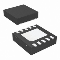
LM96163CISD/NOPB National Semiconductor, LM96163CISD/NOPB Datasheet - Page 37

LM96163CISD/NOPB
Manufacturer Part Number
LM96163CISD/NOPB
Description
IC TEMP SENSOR DGTL REMOTE 10LLP
Manufacturer
National Semiconductor
Series
PowerWise®, TruTherm®r
Datasheet
1.LM96163CISDNOPB.pdf
(42 pages)
Specifications of LM96163CISD/NOPB
Function
Fan Control, Temp Monitor
Topology
ADC (Sigma Delta), Comparator, Register Bank, Tach
Sensor Type
External & Internal
Sensing Temperature
-40°C ~ 85°C, External Sensor
Output Type
SMBus™
Output Alarm
Yes
Output Fan
Yes
Voltage - Supply
3 V ~ 3.6 V
Operating Temperature
-40°C ~ 85°C
Mounting Type
Surface Mount
Package / Case
10-LLP
Temperature Sensor Function
Temp Sensor
Interface Type
Serial (2-Wire)
Resolution
10+SignBit
Package Type
LLP EP
Operating Temperature (min)
-40C
Operating Temperature (max)
85C
Operating Supply Voltage (min)
3V
Operating Supply Voltage (typ)
3.3V
Operating Supply Voltage (max)
3.6V
Lead Free Status / RoHS Status
Lead free / RoHS Compliant
Other names
LM96163CISDTR
Available stocks
Company
Part Number
Manufacturer
Quantity
Price
Part Number:
LM96163CISD/NOPB
Manufacturer:
TI/德州仪器
Quantity:
20 000
3.4.1 Diode Non-Ideality Factor Effect on Accuracy
When a transistor is connected as a diode, the following re-
lationship holds for variables V
where:
•
•
•
•
•
•
•
In the active region, the -1 term is negligible and may be elim-
inated, yielding the following equation
In
was used in the fabrication of the particular diode. By forcing
two currents with a very controlled ratio(I
ing the resulting voltage difference, it is possible to eliminate
Equation
q = 1.6×10
T = Absolute Temperature in Kelvin
k = 1.38×10
η is the non-ideality factor of the process the diode is
manufactured on,
I
I
V
S
f
BE
= Forward Current through the base-emitter junction
= Saturation Current and is process dependent,
= Base-Emitter Voltage drop
2, η and I
−19
−23
Coulombs (the electron charge),
joules/K (Boltzmann's constant),
S
are dependant upon the process that
BE
, T and I
F2
F
:
/ I
FIGURE 8. Thermal Diode Current Paths
F1
) and measur-
(1)
(2)
37
the I
the relationship:
Solving
Equation 4
as the MMBT3904 is used. When this “diode” equation is ap-
plied to an integrated diode such as a processor transistor
with its collector tied to GND as shown in
a wide non-ideality spread. This wide non-ideality spread is
not due to true process variation but due to the fact that
Equation 4
TruTherm BJT beta compensation technology uses the tran-
sistor equation,
sentation of the topology of the thermal diode found in an
FPGA or processor.
TruTherm should only be enabled when measuring the tem-
perature of a transistor integrated as shown in the processor
of
Figure
S
term. Solving for the forward voltage difference yields
Equation 3
8, because
holds true when a diode connected transistor such
is an approximation.
Equation
for temperature yields:
Equation 5
30041043
5, which is a more accurate repre-
only applies to this topology.
Figure 8
www.national.com
it will yield
(3)
(4)
(5)


