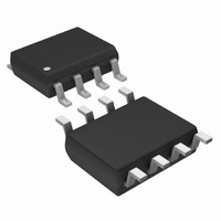
DS1821S Maxim Integrated Products, DS1821S Datasheet - Page 10

DS1821S
Manufacturer Part Number
DS1821S
Description
IC THERMOMETER/STAT PROG 8-SOIC
Manufacturer
Maxim Integrated Products
Datasheet
1.DS1821.pdf
(18 pages)
Specifications of DS1821S
Function
Thermometer, Thermostat
Topology
Comparator, Register Bank
Sensor Type
Internal
Sensing Temperature
-55°C ~ 125°C
Output Type
Digital
Output Alarm
No
Output Fan
No
Voltage - Supply
2.7 V ~ 5.5 V
Operating Temperature
-55°C ~ 125°C
Mounting Type
Surface Mount
Package / Case
8-SOIC (5.3mm Width), 8-SOP, 8-SOEIAJ
Full Temp Accuracy
+/- 1 C
Digital Output - Bus Interface
Serial (1-Wire)
Digital Output - Number Of Bits
8 bit
Maximum Operating Temperature
+ 125 C
Minimum Operating Temperature
- 55 C
Lead Free Status / RoHS Status
Contains lead / RoHS non-compliant
Available stocks
Company
Part Number
Manufacturer
Quantity
Price
Company:
Part Number:
DS1821S
Manufacturer:
DALLAS
Quantity:
8 680
Part Number:
DS1821S
Manufacturer:
DALLAS
Quantity:
20 000
Company:
Part Number:
DS1821S+
Manufacturer:
MAXIM
Quantity:
202
Company:
Part Number:
DS1821S+T&R
Manufacturer:
Sonnenschein
Quantity:
2 000
Part Number:
DS1821S+TR
Manufacturer:
MAXIM/美信
Quantity:
20 000
Company:
Part Number:
DS1821S/TR
Manufacturer:
DALLAS
Quantity:
15 368
DS1821
INITIALIZATION
All transactions on the 1-Wire bus begin with an initialization sequence. The initialization sequence
consists of a reset pulse transmitted by the bus master followed by a presence pulse transmitted by the
DS1821.
The presence pulse lets the bus master know that the DS1821 is on the bus and ready to
operate. Timing for the reset and presence pulses is detailed in the 1-Wire SIGNALING section.
DS1821 FUNCTION COMMANDS
The DS1821 function commands in this section allow the master to communicate with and configure the
DS1821. The DS1821 function commands are summarized in Table 4.
READ TEMPERATURE [AAh]
Provides read access to the 1-byte temperature register.
START CONVERT T [EEh]
Initiates temperature conversions. If the part is in one-shot mode (1SHOT = 1), only one conversion will
be performed. If it is in continuous mode (1SHOT = 0), continuous conversions will be performed until a
Stop Convert T command is received.
STOP CONVERT T [22h]
Stops temperature conversions when the device is in continuous conversion mode (1SHOT = 0). This
opcode has no function if the device is in one-shot mode (1SHOT = 1).
WRITE TH [01h]
WRITE TL [02h]
Provides write access to the 8-bit T
and T
registers, respectively.
H
L
READ TH [A1h]
READ TL [A2h]
Provides read access to the 8-bit T
and T
registers, respectively.
H
L
WRITE STATUS [0Ch]
Provides write access to the 8-bit status/configuration register.
READ STATUS [ACh]
Provides read access to the 8-bit status/configuration register.
READ COUNTER [A0h]
Provides read access to data in the 9-bit counter register for use in high-resolution temperature
calculations. This is explained in detail in the HIGH-RESOLUTION TEMPERATURE READINGS
section.
LOAD COUNTER [41h]
Loads the 9-bit data from the slope accumulator register into the counter register so that it can be accessed
using the Read Counter [A0h] command. Use of the Load Counter command is explained in detail in the
HIGH-RESOLUTION TEMPERATURE READINGS section.
10 of 18


