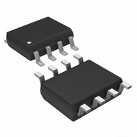
DS1821S Maxim Integrated Products, DS1821S Datasheet - Page 7

DS1821S
Manufacturer Part Number
DS1821S
Description
IC THERMOMETER/STAT PROG 8-SOIC
Manufacturer
Maxim Integrated Products
Datasheet
1.DS1821.pdf
(18 pages)
Specifications of DS1821S
Function
Thermometer, Thermostat
Topology
Comparator, Register Bank
Sensor Type
Internal
Sensing Temperature
-55°C ~ 125°C
Output Type
Digital
Output Alarm
No
Output Fan
No
Voltage - Supply
2.7 V ~ 5.5 V
Operating Temperature
-55°C ~ 125°C
Mounting Type
Surface Mount
Package / Case
8-SOIC (5.3mm Width), 8-SOP, 8-SOEIAJ
Full Temp Accuracy
+/- 1 C
Digital Output - Bus Interface
Serial (1-Wire)
Digital Output - Number Of Bits
8 bit
Maximum Operating Temperature
+ 125 C
Minimum Operating Temperature
- 55 C
Lead Free Status / RoHS Status
Contains lead / RoHS non-compliant
Available stocks
Company
Part Number
Manufacturer
Quantity
Price
Company:
Part Number:
DS1821S
Manufacturer:
DALLAS
Quantity:
8 680
Part Number:
DS1821S
Manufacturer:
DALLAS
Quantity:
20 000
Company:
Part Number:
DS1821S+
Manufacturer:
MAXIM
Quantity:
202
Company:
Part Number:
DS1821S+T&R
Manufacturer:
Sonnenschein
Quantity:
2 000
Part Number:
DS1821S+TR
Manufacturer:
MAXIM/美信
Quantity:
20 000
Company:
Part Number:
DS1821S/TR
Manufacturer:
DALLAS
Quantity:
15 368
OPERATION – THERMOSTAT
When the DS1821 is in thermostat mode (T/R ¯ = 1 in the status/configuration register), temperature
conversions are performed continuously beginning at power-up (regardless of the value of the 1SHOT
bit), and the DQ pin serves as the thermostat output.
temperature of the DS1821 exceeds the user-defined limit in the T
the temperature drops below the user-defined limit in the T
user can select T
The user-defined 8-bit centigrade trip-point values (T
format as shown in Figure 3. The sign bit (S) indicates if the temperature is positive or negative; for
positive numbers S = 0 and for negative numbers S = 1. The non-volatile T
programmed when the DS1821 is in 1-Wire mode as explained in the OPERATING MODES section of
this datasheet. The DS1821 can be temporarily switched from thermostat mode to 1-Wire mode to
change the T
The polarity (i.e., the active state) of the DQ output is user-selectable with the nonvolatile POL bit in the
status/configuration register. DQ is active-high when POL = 1, and DQ is active-low when POL = 0.
Two bits in the status/configuration register, THF and TLF, provide additional thermostatic information.
The value of these bits is normally 0. The THF (temperature high flag) bit will be set to 1 if the measured
temperature is ever greater than the value in the T
bit with a 0. The TLF (temperature low flag) bit will be set to 1 if the temperature is ever lower than the
value in the T
record of the device temperature relative to the thermostat trip-points over a period of time. They are
stored in nonvolatile memory, so the data stored in THF and TLF can be analyzed after any number of
power cycles. The THF and TLF bits function in both 1-Wire and thermostat mode.
DQ OPERATION IN THERMOSTATE MODE Figure 4
STATUS/CONFIGURATION REGISTER
The status/configuration register provides information to the user about conversion status, EEPROM
activity and thermostat activity. It also allows the user to program various DS1821 options such as
power-up operating mode, thermostat output polarity and conversion mode. The status/configuration
register is arranged as shown in Figure 5 and detailed descriptions of each bit are provided in Table 3.
Note that the THF, TLF T/R ¯ , POL and 1SHOT bits are stored in nonvolatile memory (EEPROM).
CONFIGURATION REGISTER Figure 5
H
L
and T
register and will remain a 1 until the user rewrites the bit with a 0. These bits provide a
H
and T
*
DONE
L
Stored in EEPROM
values as also explained in the OPERATING MODES section.
bit 7
L
DQ
to provide the desired amount of thermostat output hysteresis.
bit 6
1
Operating Mode = Thermostat
POL=1 (DQ is active high)
NVB THF* TLF*
T
bit 5
L
bit 4
H
7 of 18
register and will remain a 1 until the user rewrites the
bit 3
H
and T
T
The DQ output will become active when the
L
H
register as illustrated in Figure 4. Thus, the
T/R ¯ * POL* 1SHOT*
bit 2
L
) must be stored in two’s complement
H
register, and will remain active until
bit 1
Temp (°C)
H
bit 0
and T
L
registers must be


