ISL8843ABZ Intersil, ISL8843ABZ Datasheet
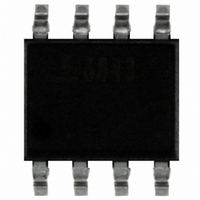
IC CTRLR PWM SGL ENDED 8-SOIC

ISL8843ABZ

Manufacturer Part Number
ISL8843ABZ
Description
IC CTRLR PWM SGL ENDED 8-SOIC
Manufacturer
Intersil
Datasheet

Specifications of ISL8843ABZ

Pwm Type
Current Mode
Number Of Outputs
1
Frequency - Max
2MHz
Duty Cycle
100%
Voltage - Supply
9 V ~ 30 V
Buck
Yes
Boost
Yes
Flyback
Yes
Inverting
No
Doubler
No
Divider
No
Cuk
No
Isolated
Yes
Operating Temperature
-40°C ~ 105°C
Package / Case
8-SOIC (3.9mm Width)
Frequency-max
2MHz
Rohs Compliant
YES
Lead Free Status / RoHS Status
Lead free / RoHS Compliant

Available stocks

Company
Part Number
Manufacturer
Quantity
Price
Part Number:
ISL8843ABZ
Manufacturer:
INTERSIL
Quantity:
20 000
Industry Standard Single-Ended Current
Mode PWM Controller
The ISL8843 is an industry standard drop-in replacement for
the popular 28C43 and 18C43 PWM controllers suitable for
a wide range of power conversion applications including
boost, flyback, and isolated output configurations. Its fast
signal propagation and output switching characteristics
make this an ideal product for existing and new designs.
Features include 30V operation, low operating current, 90µA
start-up current, adjustable operating frequency to 2MHz,
and high peak current drive capability with 20ns rise and fall
times.
Ordering Information
Add -T to part number for Tape and Reel packaging.
NOTE: Intersil Pb-free plus anneal products employ special Pb-free
material sets; molding compounds/die attach materials and 100%
matte tin plate termination finish, which are RoHS compliant and
compatible with both SnPb and Pb-free soldering operations. Intersil
Pb-free products are MSL classified at Pb-free peak reflow
temperatures that meet or exceed the Pb-free requirements of
IPC/JEDEC J STD-020.
ISL8843ABZ
(See Note)
ISL8843AUZ
(See Note)
ISL8843MBZ
(See Note)
ISL8843MUZ
(See Note)
PART NUMBER
NUMBER
PART
ISL8843
8843 ABZ
8843Z
8843 MBZ
843MZ
MARKING
PART
RISING UVLO
8.4V
®
RANGE (°C) PACKAGE
-40 to 105
-40 to 105
-55 to 125
-55 to 125
1
TEMP.
Data Sheet
MAX. DUTY CYCLE
8 Ld SOIC
(Pb-free)
8 Ld MSOP
(Pb-free)
8 Ld SOIC
(Pb-free)
8 Ld MSOP
(Pb-free)
100%
M8.15
M8.118
M8.15
M8.118
DWG. #
PKG.
1-888-INTERSIL or 1-888-468-3774
CAUTION: These devices are sensitive to electrostatic discharge; follow proper IC Handling Procedures.
Features
• 1A MOSFET gate driver
• 90µA start-up current, 125µA maximum
• 35ns propagation delay current sense to output
• Fast transient response with peak current mode control
• 30V operation
• Adjustable switching frequency to 2MHz
• 20ns rise and fall times with 1nF output load
• Trimmed timing capacitor discharge current for accurate
• 1.5MHz bandwidth error amplifier
• Tight tolerance voltage reference over line, load, and
• ±3% current limit threshold
• Pb-free plus anneal available and ELV, WEEE, RoHS
Applications
• Telecom and datacom power
• Wireless base station power
• File server power
• Industrial power systems
• PC power supplies
• Isolated buck and flyback regulators
• Boost regulators
Pinout
deadtime/maximum duty cycle control
temperature
Compliant
January 3, 2006
All other trademarks mentioned are the property of their respective owners.
|
Intersil (and design) is a registered trademark of Intersil Americas Inc.
Copyright © Intersil Americas Inc. 2005, 2006 All Rights Reserved.
COMP
RTCT
CS
FB
(8 LD SOIC, MSOP)
1
2
3
4
TOP VIEW
ISL8843
8
7
5
6
VREF
VDD
OUT
GND
ISL8843
FN9238.1

Related parts for ISL8843ABZ

ISL8843ABZ Summary of contents

Page 1

... PART NUMBER RISING UVLO ISL8843 8.4V Ordering Information PART PART TEMP. NUMBER MARKING RANGE (°C) PACKAGE ISL8843ABZ 8843 ABZ -40 to 105 (See Note) ISL8843AUZ 8843Z -40 to 105 (See Note) ISL8843MBZ 8843 MBZ -55 to 125 (See Note) ISL8843MUZ ...

Page 2

Functional Block Diagram V DD START/STOP UV COMPARATOR + - + - GND A 2.5V A=0 Total = 1.15V ERROR AMPLIFIER COMP VREF 100K 2.9V 1.0V 150K OSCILLATOR COMPARATOR < 10nS - RTCT + CLOCK ...

Page 3

Typical Application - 48V Input Dual Output Flyback VIN+ R1 36-75V C1 VIN VR1 CR2 C5 CR6 R22 R27 U4 R26 COMP VREF CS FB RTCT ISL8843 R10 CR1 C8 CR5 C21 ...

Page 4

Absolute Maximum Ratings Supply Voltage GND - 0.3V to +30.0V DD OUT . . . . . . . . ...

Page 5

Electrical Specifications ISL8843A - Typical Application schematic. V are at T PARAMETER FB Input Bias Current COMP Sink Current COMP Source Current COMP VOH COMP VOL PSRR OSCILLATOR Frequency Accuracy Frequency Variation with V DD Temperature Stability Amplitude, Peak to ...

Page 6

Electrical Specifications ISL8843M Typical Application schematic. V are at T PARAMETER Long Term Stability Current Limit, Sourcing Current Limit, Sinking CURRENT SENSE Input Bias Current CS Offset Voltage COMP to PWM Comparator Offset Voltage Input Signal, Maximum = ∆V Gain, ...

Page 7

Typical Performance Curves 1.01 1 0.99 0.98 -60 -40 - TEMPERATURE (°C) FIGURE 1. FREQUENCY vs TEMPERATURE 1.001 1.000 0.998 0.997 0.996 -60 -40 - TEMPERATURE (°C) FIGURE 3. EA REFERENCE vs ...

Page 8

OUT - This is the drive output to the power switching device high current output capable of driving the gate of a power MOSFET with peak currents of 1.0A. This GATE output is actively held low when ...

Page 9

The double-pole will be critically damped if the Q-factor is set to 1, over-damped for Q < 1, and under- damped for Q > under-damped condition may result in current loop instability ------------------------------------------------- = π ...

Page 10

Example 12V 48V 800µH s Ns/ 8.0µ 200mA O Switching Frequency, Fsw = 200kHz Duty Cycle 28. 499Ω Solve for the current ...

Page 11

Small Outline Plastic Packages (SOIC) N INDEX 0.25(0.010) H AREA E - SEATING PLANE - -C- α 0.10(0.004) 0.25(0.010 NOTES: 1. Symbols are defined in the ...

Page 12

... Accordingly, the reader is cautioned to verify that data sheets are current before placing orders. Information furnished by Intersil is believed to be accurate and reliable. However, no responsibility is assumed by Intersil or its subsidiaries for its use; nor for any infringements of patents or other rights of third parties which may result from its use ...

Related keywords