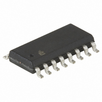
ISL6722AABZ Intersil, ISL6722AABZ Datasheet - Page 12

ISL6722AABZ
Manufacturer Part Number
ISL6722AABZ
Description
IC CTRLR PWM SGL ENDED 16-SOIC
Manufacturer
Intersil
Datasheet
1.ISL6722AAVZ.pdf
(24 pages)
Specifications of ISL6722AABZ
Pwm Type
Current Mode
Number Of Outputs
1
Frequency - Max
1MHz
Duty Cycle
100%
Voltage - Supply
9 V ~ 18 V
Buck
Yes
Boost
Yes
Flyback
Yes
Inverting
No
Doubler
No
Divider
No
Cuk
No
Isolated
Yes
Operating Temperature
-40°C ~ 105°C
Package / Case
16-SOIC (3.9mm Width)
Frequency-max
1MHz
Lead Free Status / RoHS Status
Lead free / RoHS Compliant
Available stocks
Company
Part Number
Manufacturer
Quantity
Price
Part Number:
ISL6722AABZ
Manufacturer:
INTERSIL
Quantity:
20 000
Part Number:
ISL6722AABZ-T
Manufacturer:
INTERS
Quantity:
20 000
For flyback topologies, V
output voltage, current transducer components, and primary
inductance yielding:
V
where R
current transformer turns ratio, L
V
and primary turns, respectively. If a current transformer is not
used, then N
For discussion purposes, only the flyback topology will be
further discussed. A discussion addressing the buck derived
topologies may be found in the datasheet for the ISL6753.
The current sense signal, which represents the primary
current after it has been reflected through the current sense
transformer and passed through the current sense burden
resistor, is:
V
where V
and I
Since the peak current limit threshold is determined by ISET,
the total current feedback signal plus the external ramp
voltage must sum to this value when the output load is at the
current limit threshold.
V
where the internal gain and offset voltages of the IC have
been included. Substituting Equations 15 and 17 into
Equation 18 and solving for R
R
Adding slope compensation is accomplished in the
ISL6722A, ISL6723A using the SLOPE input. The value of
Ve determined in Equation 16, multiplied 10x, is the voltage
required at the SLOPE input.
C
where I
nominally 53µA.
Over and Undervoltage Monitor
The OV and UV signals are inputs to a window comparator
used to monitor the input voltage level to the converter. If the
e
CS
e
O
CS
SLOPE
+
=
is the output voltage, and N
(
=
O
=
V
t
--------------------------------------- -
SW
CS
R
----------- - I
N
is the output current at current limit.
-----------------------------------------------------------------------------------------------------------------------
T
------------------------------------- -
SLOPE
CS
N
CS
SW
CS
CT
=
⋅
⋅
CT
L
V
0.8
I
---------------------------------- -
⎛
⎜
⎝
P
is the voltage across the current sense resistor
SLOPE
is the current sense burden resistor, N
O
⋅
⎛
⎜
⎝
CT
⋅
V
⋅
)
⋅
L
O
V
N
O
is the internal charging current on SLOPE,
R
+
P
e
⋅
S
= 1.
⋅
CS
0.100
N
------- -
N
⋅
N
10
S
P
⋅
(
P
⋅
⎞
⎟
⎠
t
ISET 0.1
ON
N
------- -
N
⋅
+
⎛
⎝
P
S
=
1
-- -
π
(
--------------------------------------------- -
1 D
⎛
⎝
+
1
-- -
π
n
ISET
–
–
0.6D 0.1
+
can be solved for in terms of
D 0.5
) V
2L
12
⋅
CS
) N
–
⋅
–
P
S
O
P
and N
yields
CT
⋅
⎞
⎠
is the primary inductance,
t
⎞
⎠
SW
+
0.8I
⋅
P
N
------- -
N
V
are the secondary
P
S
O
⎞
⎟
⎠
⋅
N
------- -
N
S
P
V
CT
ISL6722A, ISL6723A
Ω
(EQ. 16)
(EQ. 17)
(EQ. 19)
(EQ. 20)
(EQ. 18)
is the
voltage falls outside of the user designated operating range,
a shutdown fault occurs. For OV faults, the supply current,
I
is attempted. If the fault is cleared, a soft-start cycle begins.
Otherwise another shutdown cycle occurs. A UV condition
also results in a shutdown fault, but the device does not
enter the low power mode and no restart delay occurs when
the fault clears.
A resistor divider between Vin and LGND to each input
determines the operational thresholds. The UV threshold
has a fixed hysteresis of 75mV nominal.
Overcurrent Operation
The overcurrent threshold level is set by the voltage applied
at the ISET pin. Setting the overcurrent level may be
accomplished by using a resistor divider network from VREF
to LGND. The ISET threshold should be set at a level that
corresponds to the desired peak output inductor current plus
the additive effects of slope compensation.
Overcurrent delayed shutdown is enabled once the soft-start
cycle is complete. If an overcurrent condition is detected, the
soft-start charging current source is disabled and the
discharging current source is enabled. The soft-start
capacitor is discharged at a rate of 40µA. At the same time a
50µs retriggerable one-shot timer is activated. It remains
active for 50µs after the overcurrent condition stops. The
soft-start discharge cycle cannot be reset until the one-shot
timer becomes inactive. If the soft-start capacitor discharges
by more then 0.125V to 4.375V, the output is disabled and
the soft-start capacitor is discharged. The output remains
disabled and I
A new soft-start cycle is then initiated. The shutdown and
restart behavior of the OC protection is often referred to as
hiccup operation due to its repetitive start-up and shutdown
characteristic.
If the overcurrent condition ceases at least 50µs prior to the
soft-start voltage reaching 4.375V, the soft-start charging
and discharging currents revert to normal operation and the
soft-start voltage is allowed to recover.
Hiccup OC protection may be defeated by setting ISET to a
voltage that exceeds the Error Amplifier current control
voltage, or about 1.5V.
CC
, is reduced to 200µA for ~ 295ms at which time recovery
CC
drops to 200µA for approximately 295ms.
July 11, 2007
FN9237.1


