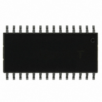
ISL6551IB Intersil, ISL6551IB Datasheet - Page 18

ISL6551IB
Manufacturer Part Number
ISL6551IB
Description
IC CNTRLR PWM FULL BRIDGE 28SOIC
Manufacturer
Intersil
Datasheet
1.ISL6551IBZ.pdf
(26 pages)
Specifications of ISL6551IB
Pwm Type
Current Mode
Number Of Outputs
6
Frequency - Max
1MHz
Duty Cycle
50%
Voltage - Supply
10.8 V ~ 13.2 V
Buck
No
Boost
No
Flyback
Yes
Inverting
No
Doubler
No
Divider
No
Cuk
No
Isolated
No
Operating Temperature
0°C ~ 85°C
Package / Case
28-SOIC (7.5mm Width)
Frequency-max
1MHz
Lead Free Status / RoHS Status
Contains lead / RoHS non-compliant
Available stocks
Company
Part Number
Manufacturer
Quantity
Price
Company:
Part Number:
ISL6551IB
Manufacturer:
HARRIS
Quantity:
66
Company:
Part Number:
ISL6551IB
Manufacturer:
INTERSIL
Quantity:
18
Company:
Part Number:
ISL6551IB
Manufacturer:
INTERSIL
Quantity:
18
Part Number:
ISL6551IB
Manufacturer:
HAR
Quantity:
20 000
Company:
Part Number:
ISL6551IBZ
Manufacturer:
JRC
Quantity:
1 032
Current Sense
Two-Leg Sense - Senses the current that flows through both
lower primary FETs. Operates at the switching frequency.
Top Sense - Senses the sum of the current that flows through
both upper primary FETs. Operates at the clock frequency.
Resistor Sense - This simple scheme is used in a primary side
control system. The sum of the current that flows through both
lower primary FETs is sensed with a low impedance power
resistor. The sources of Q3 and Q4 and ISENSE should be tied
at the same point as close as possible.
BIASES
Linear Regulator - In a primary side control system, a
linear regulator derived from the input line can be used for
the start-up purpose, and an extra winding coupled with the
main transformer can provide the controller power after the
start up.
DCM Flyback - Use a PWM controller to develop both
primary and secondary biases with discontinuous current
mode flyback topology.
Q3_S
Q4_S
FIGURE 14C. RESISTOR SENSE (PRIMARY CONTROL)
CURRENT_SEN_P
Q3_S & Q4_S
T_CURRENT
FIGURE 14A. TWO-LEG SENSE
V
FIGURE 14B. TOP SENSE
IN
F
RSENSE
18
ISENSE
ISENSE
ISENSE
ISL6551
Primary FETs
Full Bridge - Four MOSFETs are required for full bridge
converters. The drain to source voltage rating of the
MOSFETs is Vin.
Push-Pull - Only the two lower MOSFETs are required for
push-pull converters. The two upper drivers are not used.
The V
or CURRENT_SEN_P
V
IN
DS
F
of the MOSFETs is 2xVin.
Q3_G
Q1_G
Q3_G
P–
FIGURE 15A.
FIGURE 15B.
Q3_S
Q3_S
P1–
Q3
Q1
Q3
FULL BRIDGE
PUSH-PULL
Q4_G
Q2_G
P+
Q4_G
Q4_S
Q4_S
P2–
Q2
January 3, 2006
Q4
Q4
FN9066.5


