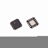
ISL6410AIR Intersil, ISL6410AIR Datasheet - Page 5

ISL6410AIR
Manufacturer Part Number
ISL6410AIR
Description
IC REG PWM SYNC BUCK 5V 16QFN
Manufacturer
Intersil
Type
Step-Down (Buck), PWM - Current Moder
Datasheet
1.ISL6410AIUZ-TK.pdf
(13 pages)
Specifications of ISL6410AIR
Internal Switch(s)
Yes
Synchronous Rectifier
Yes
Number Of Outputs
1
Voltage - Output
1.2V, 1.8V, 3.3V
Current - Output
600mA
Frequency - Switching
750kHz
Voltage - Input
3 ~ 3.6 V
Operating Temperature
-40°C ~ 85°C
Mounting Type
*
Package / Case
16-VQFN Exposed Pad, 16-HVQFN, 16-SQFN, 16-DHVQFN
Voltage - Supply
4.5 V ~ 5.5 V
Frequency-max
860kHz
Duty Cycle
93%
Pwm Type
Current Mode
Buck
Yes
Boost
No
Flyback
No
Inverting
No
Doubler
No
Divider
No
Cuk
No
Isolated
No
Lead Free Status / RoHS Status
Contains lead / RoHS non-compliant
Available stocks
Company
Part Number
Manufacturer
Quantity
Price
Company:
Part Number:
ISL6410AIR
Manufacturer:
Intersil
Quantity:
500
Company:
Part Number:
ISL6410AIRZ
Manufacturer:
Intersil
Quantity:
150
Absolute Maximum Ratings
Supply Voltage, V
SYNC, FB, VSET & Enable Input (Note 3) . . . . -0.3V to VCC+0.3V
ESD Classification (Human Body Model) . . . . . . . . . . . . . . . Class 2
CAUTION: Stresses above those listed in “Absolute Maximum Ratings” may cause permanent damage to the device. This is a stress only rating and operation of the
device at these or any other conditions above those indicated in the operational sections of this specification is not implied.
NOTES:
Electrical Specifications
V
Supply Voltage Range
Input UVLO Threshold
Quiescent Supply Current
Shutdown Supply Current
Thermal Shutdown Temperature (Note 7)
Thermal Shutdown Hysteresis (Note 7)
SYNCHRONOUS BUCK PWM REGULATOR
Output Voltage
Output Voltage Accuracy
Line Regulation
Load Regulation
Maximum Output Current
Peak Output Current Limit
PMOS r
NMOS r
Efficiency
3. All voltages are with respect to GND.
4. θ
5. For θ
CC
Tech Brief TB379.
JA
SUPPLY
is measured in free air with the component mounted on a high effective thermal conductivity test board with “direct attach” features. See
DS(ON)
DS(ON)
JC
, the “case temp” location is the center of the exposed metal pad on the package underside.
PARAMETER
CC
. . . . . . . . . . . . . . . . . . . . . . . . . -0.3V to +6.0V
5
Recommended operating conditions unless otherwise noted. V
(ISL6410A), T
VIN (ISL6410)
VIN (ISL6410A)
V
V
V
V
I
EN = GND, T
EN = GND, T
Rising Threshold
ISL6410, VSET = L
ISL6410, VSET = H
ISL6410, VSET = OPEN
ISL6410A, VSET = L
ISL6410A, VSET = H
ISL6410A, VSET = OPEN
I
I
I
I
I
I
OUT
OUT
OUT
OUT
OUT
OUT
OUT
A
TR
TF
TR
TF
= 25°C (Note 6).
(ISL6410) Falling
(ISL6410A) Falling
(ISL6410) Rising
(ISL6410A) Rising
= 0mA
= 3mA, T
= 3mA
= 3mA to 600mA
= 200mA
= 200mA
= 200mA, V
ISL6410, ISL6410A
A
A
A
TEST CONDITIONS
= 25°C
= 85°C
= -40°C to 85°C
IN
= 3.3V, V
O
Thermal Information
Thermal Resistance (Typical)
Maximum Junction Temperature (Plastic Package) . . . . . . . . 150°C
Maximum Storage Temperature Range . . . . . . . . . . . -65°C to 150°C
Maximum Lead Temperature (10s, soldering . . . . . . . . . . . . . 260°C
Ambient Temperature Range. . . . . . . . . . . . . . . . . . . . -40°C to 85°C
Junction Temperature Range. . . . . . . . . . . . . . . . . . . -40°C to 125°C
= 1.8V (ISL6410)
MSOP Package (Note 4) . . . . . . . . . . .
QFN Package (Notes 4, 5). . . . . . . . . .
IN
= 3.3V ±10% (ISL6410) or 5V ±10%
MIN
2.62
2.53
4.27
-1.5
-0.5
-1.5
700
3.0
4.5
4.1
-
-
-
-
-
-
-
-
-
-
-
-
-
-
-
TYP
2.68
2.59
4.37
4.22
150
230
230
3.3
5.0
2.3
1.2
1.8
1.5
1.2
3.3
1.8
10
20
92
5
-
-
-
-
-
θ
JA
MAX
1300
128
2.73
2.64
4.45
4.32
+1.5
+0.5
+1.5
600
(°C/W)
45
3.6
5.5
10
15
25
-
-
-
-
-
-
-
-
-
-
-
θ
JC
UNITS
mΩ
mΩ
mA
mA
mA
µA
µA
°C
°C
%
%
%
%
V
NA
7.5
V
V
V
V
V
V
V
V
V
V
V
(°C/W)


