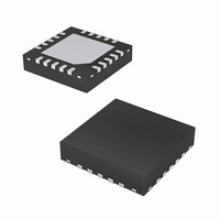
EL7586AILZ-T13 Intersil, EL7586AILZ-T13 Datasheet - Page 9

EL7586AILZ-T13
Manufacturer Part Number
EL7586AILZ-T13
Description
IC POWER SUPPLY TFT-LCD 20-QFN
Manufacturer
Intersil
Datasheet
1.EL7586AILZ-T13.pdf
(21 pages)
Specifications of EL7586AILZ-T13
Applications
Converter, TFT, LCD
Voltage - Input
3 ~ 5 V
Number Of Outputs
4
Voltage - Output
5.5 ~ 20 V
Operating Temperature
-40°C ~ 85°C
Mounting Type
Surface Mount
Package / Case
20-VQFN Exposed Pad, 20-HVQFN, 20-SQFN, 20-DHVQFN
Lead Free Status / RoHS Status
Lead free / RoHS Compliant
Applications Information
The EL7586 and EL7586A provide a high integrated multiple
output power solution for TFT-LCD applications. The system
consists of one high efficiency boost converter and three
linear-regulator controllers (V
multiple protection functions. A block diagram is shown in
Figure 25. Table 1 lists the recommended components.
The EL7586, and EL7586A integrate an N-channel
MOSFET boost converter to minimize external component
count and cost. The A
voltages are independently set using external resistors.
V
are post regulated using the integrated LDO controllers.
ON
DESIGNATION
D
C
11
, V
C
1
, D
20
, C
OFF
D
Q
Q
Q
Q
Q
L
, C
12
1
2
1
1
4
3
2
5
TABLE 1. RECOMMENDED COMPONENTS
, C
, D
31
voltages require external charge pumps which
3
21
10µF, 16V X7R ceramic capacitor (1206)
TDK C3216X7RIC106M
4.7µF, 25V X5R ceramic capacitor (1206)
TDK C3216X5R1A475K
1A 20V low leakage Schottky rectifier (CASE
457-04) ON SEMI MBRM120ET3
200mA 30V Schottky barrier diode (SOT-23)
Fairchild BAT54S
6.8µH 1.3A Inductor
TDK SLF6025T-6R8M1R3-PF
-2.4 -20V P-channel 1.8V specified
PowerTrench MOSFET (SuperSOT-3)
Fairchild FDN304P
-2A -30V single P-channel logic level
PowerTrench MOSFET (SuperSOT-3)
Fairchild FDN360P
200mA 40V PNP amplifier (SOT-23)
Fairchild MMBT3906
200mA 40V NPN amplifier (SOT-23)
Fairchild MMBT3904
1A 30V PNP low saturation amplifier (SOT-23)
Fairchild FMMT549
VDD
, V
ON
ON
9
, V
, V
DESCRIPTION
OFF
OFF
, and V
, and V
LOGIC
LOGIC
) with
EL7586, EL7586A
output
Boost Converter
The main boost converter is a current mode PWM converter
at a fixed frequency of 1MHz which enables the use of low
profile inductors and multiplayer ceramic capacitors. This
results in a compact, low cost power system for LCD panel
design.
The EL7586 and EL7586A are designed for continuous
current mode, but they can also operate in discontinuous
current mode at light load. In continuous current mode,
current flows continuously in the inductor during the entire
switching cycle in steady state operation. The voltage
conversion ratio in continuous current mode is given by:
Where D is the duty cycle of the switching MOSFET.
Figure 26 shows the block diagram of the boost regulator. It
uses a summing amplifier architecture consisting of GM
stages for voltage feedback, current feedback and slope
compensation. A comparator looks at the peak inductor
current cycle by cycle and terminates the PWM cycle if the
current limit is reached.
An external resistor divider is required to divide the output
voltage down to the nominal reference voltage. Current
drawn by the resistor network should be limited to maintain
the overall converter efficiency. The maximum value of the
resistor network is limited by the feedback input bias current
and the potential for noise being coupled into the feedback
pin. A resistor network in the order of 60kΩ is recommended.
The boost converter output voltage is determined by the
following equation:
The current through the MOSFET is limited to 2A peak for
the EL7586. This restricts the maximum output current
based on the following equation:
I
Where ∆IL is peak to peak inductor ripple current, and is set
by:
where f
A
--------------- -
A
OMAX
∆I
V
VDD
VDD
IN
L
=
=
=
=
V
---------
S
L
IN
R
-------------------- -
------------ -
1 D
is the switching frequency.
I
1
1
–
LMT
R
×
+
1
---- -
f
D
R
S
2
–
×
∆I
--------
2
V
L
REF
×
V
---------
V
IN
O
January 17, 2006
FN9210.2


