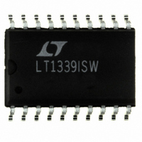
LT1339ISW#PBF Linear Technology, LT1339ISW#PBF Datasheet - Page 12

LT1339ISW#PBF
Manufacturer Part Number
LT1339ISW#PBF
Description
IC DC/DC CONTROLLER HIPWR 20SOIC
Manufacturer
Linear Technology
Type
Step-Up (Boost)r
Datasheet
1.LT1339CNPBF.pdf
(20 pages)
Specifications of LT1339ISW#PBF
Internal Switch(s)
No
Synchronous Rectifier
Yes
Number Of Outputs
1
Current - Output
65mA
Frequency - Switching
150kHz
Voltage - Input
Up to 60V
Operating Temperature
-40°C ~ 85°C
Mounting Type
Surface Mount
Package / Case
20-SOIC (7.5mm Width)
Primary Input Voltage
60V
No. Of Outputs
1
Output Voltage
54V
Output Current
65mA
No. Of Pins
20
Operating Temperature Range
-40°C To +85°C
Msl
MSL 1 - Unlimited
Rohs Compliant
Yes
Lead Free Status / RoHS Status
Lead free / RoHS Compliant
Voltage - Output
-
Power - Output
-
Available stocks
Company
Part Number
Manufacturer
Quantity
Price
APPLICATIONS
LT1339
the converter input supply is enabled with no voltage on
the LT1339 12V
will not be activated. To prevent turn-on, an external
current path must be used to bleed off charge on the
switch MOSFET gates. High value bleed resistors (50k to
250k) should be connected between the TG and SW pins
and between BG and PGND. This provides discharge paths
for the switch MOSFET gates, preventing parasitic turn-on
and damage to the MOSFETs.
Inductor Selection
The inductor for an LT1339 converter is selected based on
output power, operating frequency and efficiency require-
ments. Generally, the selection of inductor value can be
reduced to desired maximum ripple current in the inductor
( I). For a buck converter, the minimum inductor value for
a desired maximum operating ripple current can be deter-
mined using the following relation:
where f
(L), the peak inductor current is the sum of the average
inductor current (I
( I), or:
The inductor core type is determined by peak current and
efficiency requirements. The inductor core must with-
stand peak current without saturating, and series winding
resistance and core losses should be kept as small as is
practical to maximize conversion efficiency.
The LT1339 peak current limit threshold is 40% greater than
the average current limit threshold. Slope compensation
effects reduce this margin as duty cycle increases. This
margin must be maintained to prevent peak current limit
from corrupting the programmed value for average current
limit. Programming the peak ripple current to less than 15%
of the desired average current limit value will assure porper
operation of the average current limit feature through 90%
duty cycle (see Slope Compensation section).
12
L
I
PK
MIN
O
I
AVG
= operating frequency. Given an inductor value
V
OUT
IN
V
I f V
OUT
AVG
pin, the LT1339 driver output clamps
V
U
2
O
IN
)and half the inductor ripple current
L f V
V
IN
V
INFORMATION
IN
O
U
OUT
V
IN
OUT
W
U
Oscillator Synchronization
The LT1339 oscillator generates a modified sawtooth
waveform at the C
of about 0.8V (vl) and 2.5V (vh) respectively. The oscillator
can be synchronized by driving a TTL level pulse into the
SYNC pin. This inputs to a one-shot circuit that reduces the
oscillator high threshold to 2V for about 200ns. The SYNC
input signal should have minimum high/low times of 1 s.
Slope Compensation
Current mode switching regulators that operate with a
duty cycle greater than 50% and have continuous inductor
current can exhibit duty cycle instability. While a regulator
will not be damaged and may even continue to function
acceptably during this type of subharmonic oscillation, an
irritating high-pitched squeal is usually produced.
The criterion for current mode duty cycle instability is met
when the increasing slope of the inductor ripple current is
less than the decreasing slope, which is the case at duty
cycles greater than 50%. This condition is illustrated in
Figure 5a. The inductor ripple current starts at I
beginning of each oscillator switch cycle. Current
increases at a rate S1 until the current reaches the control
trip level I
main switch (and enables the synchronous switch) and
inductor current begins to decrease at a rate S2. If the
current switch point (I
increased by I, the cycle time ends such that the mini-
mum current point is increased by a factor of (1 + S2/S1)
to start the next cycle. On each successive cycle, this error
is multiplied by a factor of S2/S1. Therefore, if S2/S1 is
2.5V
0.8V
1, the system is unstable.
2V
Figure 4. Free Run and Synchronized Oscillator
Waveforms (at C
2
FREE RUN
. The controller servo loop then disables the
T
pin between low and high thresholds
T
Pin)
2
) is perturbed slightly and
SYNCHRONIZED
sn1339 1339fas
1339 F04
1
SYNC
(vh)
V
(vl)
, at the
CT


