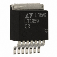
LT1959CR#TRPBF Linear Technology, LT1959CR#TRPBF Datasheet - Page 21

LT1959CR#TRPBF
Manufacturer Part Number
LT1959CR#TRPBF
Description
IC SW REG STEP-DWN 500KHZ 7-DD
Manufacturer
Linear Technology
Type
Step-Down (Buck)r
Datasheet
1.LT1959CS8PBF.pdf
(24 pages)
Specifications of LT1959CR#TRPBF
Internal Switch(s)
Yes
Synchronous Rectifier
No
Number Of Outputs
1
Voltage - Output
1.21 ~ 38 V
Current - Output
4.5A
Frequency - Switching
500kHz
Voltage - Input
4.3 ~ 15 V
Operating Temperature
0°C ~ 125°C
Mounting Type
Surface Mount
Package / Case
D²Pak, TO-263 (7 leads + tab)
Dc To Dc Converter Type
Step Down
Pin Count
7 +Tab
Input Voltage
16V
Output Voltage
1.21 to 2.42V
Switching Freq
540kHz
Output Current
8.5A
Package Type
DDPAK
Output Type
Adjustable
Switching Regulator
Yes
Line Regulation
0.03%/V
Mounting
Surface Mount
Input Voltage (min)
4V
Operating Temperature Classification
Commercial
Lead Free Status / RoHS Status
Lead free / RoHS Compliant
Power - Output
-
Lead Free Status / Rohs Status
Compliant
Available stocks
Company
Part Number
Manufacturer
Quantity
Price
APPLICATIONS
The output of the regulator contains both the desired low
frequency transient information and a reasonable amount
of high frequency (500kHz) ripple. The ripple makes it
difficult to observe the small transient, so a two-pole,
100kHz filter has been added. This filter is not particularly
critical; even if it attenuated the transient signal slightly,
this wouldn’t matter because amplitude is not critical.
After verifying that the setup is working correctly, I start
varying load current and input voltage to see if I can find
any combination that makes the transient response look
suspiciously “ringy.” This procedure may lead to an
adjustment for best loop stability or faster loop transient
response. Nearly always you will find that loop response
looks better if you add in several k for R
if necessary, because as explained before, R
may require the addition of C
everything looks OK, I use a heat gun and cold spray on the
circuit (especially the output capacitor) to bring out any
temperature-dependent characteristics.
10mV/DIV
5A/DIV
Figure 14. Loop Stability Check
INPUT SUPPLY
U
ADJUSTABLE
0.2ms/DIV
INFORMATION
U
F
to control V
W
REGULATOR
SWITCHING
1375/76 F14
ADJUSTABLE
C
C
DC LOAD
Figure 13. Loop Stability Test Circuit
. Do this only
V
500mA
BEFORE FILTER
V
AFTER FILTER
LOAD PULSE
THROUGH 50
f 780Hz
V
500mA
AFTER FILTER
OUT
OUT
pin ripple. If
OUT
C
U
AT I
AT I
AT I
above 1k
OUT
OUT
OUT
=
= 50mA
=
+
50
100Hz TO 1kHz
100mV TO 1V
100 F TO
1000 F
TO
OSCILLOSCOPE
SYNC
Keep in mind that this procedure does not take initial
component tolerance into account. You should see fairly
clean response under all load and line conditions to ensure
that component variations will not cause problems. One
note here: according to Murphy, the component most
likely to be changed in production is the output capacitor,
because that is the component most likely to have manu-
facturer variations (in ESR) large enough to cause prob-
lems. It would be a wise move to lock down the sources of
the output capacitor in production.
A possible exception to the “clean response” rule is at very
light loads, as evidenced in Figure 14 with I
Switching regulators tend to have dramatic shifts in loop
response at very light loads, mostly because the inductor
current becomes discontinuous. One common result is very
slow but stable characteristics. A second possibility is low
phase margin, as evidenced by ringing at the output with
transients. The good news is that the low phase margin at
light loads is not particularly sensitive to component varia-
tion, so if it looks reasonable under a transient test, it will
probably not be a problem in production. Note that fre-
quency of the light load ringing may vary with component
tolerance but phase margin generally hangs in there.
CURRENT SHARING MULTIPHASE SUPPLY
The circuit in Figure 15 uses multiple LT1959s to produce
a 2.5V, 12A power supply. There are several advantages to
using a multiple switcher approach compared to a single
larger switcher. The inductor size is considerably reduced.
Three 4A inductors store less energy (LI
coil so are far smaller. In addition, synchronizing three
P-P
3300pF
470
RIPPLE FILTER
4.7k
1595 F13
330pF
TO X1
OSCILLOSCOPE
PROBE
2
/2) than one 12A
LOAD
LT1959
= 50mA.
21


