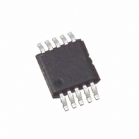
EL7515IYZ-T13 Intersil, EL7515IYZ-T13 Datasheet - Page 7

EL7515IYZ-T13
Manufacturer Part Number
EL7515IYZ-T13
Description
IC REG PWM STEP-UP 10-MSOP
Manufacturer
Intersil
Type
Step-Up (Boost)r
Datasheet
1.EL7515IYZ.pdf
(9 pages)
Specifications of EL7515IYZ-T13
Internal Switch(s)
Yes
Synchronous Rectifier
No
Number Of Outputs
1
Voltage - Output
4.5 ~ 17 V
Current - Output
600mA
Frequency - Switching
670kHz
Voltage - Input
1.8 ~ 13.2 V
Operating Temperature
-40°C ~ 85°C
Mounting Type
Surface Mount
Package / Case
10-MSOP, Micro10™, 10-uMAX, 10-uSOP
Lead Free Status / RoHS Status
Lead free / RoHS Compliant
Power - Output
-
At very low load, the MOSFET will skip pulses sometimes.
This is normal.
Current Limit
The MOSFET current limit is nominally 1.4A and guaranteed
1A. This restricts the maximum output current I
on Equation 1:
where:
• ΔI
• D is the MOSFET turn-on ratio and is decided by
• f
The following table gives typical values:
Component Considerations
It is recommended that C
Theoretically, the input capacitor has a ripple current of ΔI
Due to high-frequency noise in the circuit, the input current
ripple may exceed the theoretical value. A larger capacitor
will reduce the ripple further.
I
ΔI
D
OMAX
L
decided by Equation 2:
Equation 3:
=
S
=
L
V
(V)
3.3
3.3
3.3
is the switching frequency
12
V
----------------------- -
2
2
2
5
5
9
TABLE 1. MAX CONTINUOUS OUTPUT CURRENTS
IN
is the inductor peak-to-peak current ripple and is
V
---------
O
=
L
V
IN
–
O
⎛
⎝
V
×
1
IN
---- -
f
–
D
S
ΔI
--------
2
L
⎞
⎠
V
(V)
12
12
12
12
15
5
9
5
9
9
×
O
V
---------
V
IN
O
IN
is larger than 10µF.
(µH)
10
10
10
10
10
10
10
10
10
10
L
7
(kHz)
1000
1000
1000
1000
1000
1000
1000
1000
1000
100
F
S
OMAX
I
OMAX
(mA)
360
190
140
600
310
230
470
340
630
670
based
(EQ. 2)
(EQ. 3)
(EQ. 1)
L
.
EL7515
I
The inductor has peak and average current decided by
Equations 4 and 5:
The inductor should be chosen to be able to handle this
current. Furthermore, due to the fixed internal
compensation, it is recommended that maximum inductance
of 10µH and 15µH to be used in the 5V and 12V or higher
output voltage, respectively.
The output diode has an average current of I
current the same as the inductor's peak current. A Schottky
diode is recommended and it should be able to handle those
currents.
The output voltage ripple can be calculated as Equation 6:
ΔV
Where:
• C
• The ESR is the output capacitor ESR value.
Low ESR capacitors should be used to minimize the output
voltage ripple. Multilayer ceramic capacitors (X5R and X7R)
are preferred for the output capacitors since they have a low
ESR and small packages. Tantalum capacitors also can be
used, but they take more board space and have higher ESR.
A minimum of 22µF output capacitor is sufficient for high
output current application. For lower output current, the
output capacitor can be smaller, like 4.7µF. The capacitor
should always have enough voltage rating. In addition to the
voltage rating, the output capacitor should also be able to
handle the RMS current which is given by Equation 7:
Output Voltage
An external resistor divider is required to divide the output
voltage down to the nominal reference voltage. The current
drawn by the resistor network should be limited to maintain
the overall converter efficiency. The maximum value of the
resistor network is limited by the feedback input bias current
and the potential for noise being coupled into the feedback
pin. A resistor network less than 300kΩ is recommended.
I
I
CORMS
LPK
LAVG
O
O
=
=
is the output capacitance.
=
I
--------------------- -
F
LAVG
I
S
=
O
------------ -
1 D
I
×
–
×
O
C
1 (
D
O
+
–
ΔI
--------
+
D )
2
I
L
LPK
×
⎛
⎜
⎜
⎝
×
D
ESR
+
------------------- -
I
LAVG
ΔI
L
2
2
×
----- -
12
1
⎞
⎟
⎟
⎠
×
I
LAVG
O
, and peak
August 10, 2007
FN7120.2
(EQ. 5)
(EQ. 4)
(EQ. 6)
(EQ. 7)


