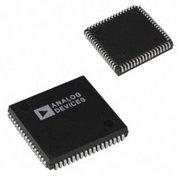
ADMC201AP Analog Devices Inc, ADMC201AP Datasheet - Page 5

ADMC201AP
Manufacturer Part Number
ADMC201AP
Description
IC MOTION CO-PROC 25MHZ 68PLCC
Manufacturer
Analog Devices Inc
Datasheet
1.ADMC201AP.pdf
(15 pages)
Specifications of ADMC201AP
Rohs Status
RoHS non-compliant
Applications
*
Mounting Type
Surface Mount
Package / Case
68-PLCC
Operating Temperature (min)
-40C
Operating Temperature (max)
85C
Operating Temperature Classification
Industrial
Mounting
Surface Mount
Lead Free Status / RoHS Status
Not Compliant
Available stocks
Company
Part Number
Manufacturer
Quantity
Price
REV. B
Pin
1
2
3
4
5
6
7
8
9
10
11
12
13
14
15
16
17
18
19
20
21
22
23
24
25
26
27
28
29
30
31
32
33
34
35
36
37
Mnemonic Type
D9
D10
D11
PIO0
PIO1
PIO2
PIO3
PIO4
PIO5
V
A3
A2
A1
A0
NC
RESET
CONVST
IRQ
V
DGND
CLK
WR
RD
CS
NC
V
AGND
AGND
U
V
W
SGND
REFIN
AUX3
AUX2
AUX1
AUX0
DD
DD
DD
BIDIR
BIDIR
BIDIR
BIDIR
BIDIR
BIDIR
BIDIR
BIDIR
BIDIR
SUP
I/P
I/P
I/P
I/P
I/P
I/P
O/P
SUP
GND
I/P
I/P
I/P
I/P
SUP
GND
GND
I/P
I/P
I/P
GND
I/P
I/P
I/P
I/P
I/P
Data Bit 9
Data Bit 10
Data Bit 11, MSB
Programmable Digital I/O Bit 0
Programmable Digital I/O Bit 1
Programmable Digital I/O Bit 2
Programmable Digital I/O Bit 3
Programmable Digital I/O Bit 4
Programmable Digital I/O Bit 5
Address Bit 3, MSB
Address Bit 2
Address Bit 1
Address Bit 0, LSB
A/D Conversion Start
Digital Ground
External Clock Input
Analog Ground
Analog Ground
Analog Signal Ground
Analog Reference Input
Auxiliary Analog Input 3
Auxiliary Analog Input 2
Auxiliary Analog Input 1
Auxiliary Analog Input 0
Description
+5 V Digital Power Supply
No Connect
Chip Reset
Interrupt Request (Pull-Up Required)
+5 V Digital Power Supply
Write Select
Output Enable/Read
Chip Select
No Connect
+5 V Analog Power Supply
Analog Input U
Analog Input V
Analog Input W
CONVST
RESET
NC = NO CONNECT
DGND
CLK
V
V
V
IRQ
WR
NC
RD
CS
NC
A3
A2
A1
A0
DD
DD
DD
10
11
12
13
14
15
16
17
18
19
20
21
22
23
24
25
26
27
9
28 29 30 31 32 33 34 35 36 37 38 39 40 41 42
8
7
PIN CONFIGURATION
6
PIN DESIGNATIONS
5
4
3
(Not to Scale)
ADMC201
TOP VIEW
2
–5–
1
68 67 66 65 64 63 62
PIN 1
IDENTIFIER
Pin
38
39
40
41
42
43
44
45
46
47
48
49
50
51
52
53
54
55
56
57
58
59
60
61
62
63
64
65
66
67
68
Pin Types
I/P = Input Pin
O/P = Output Pin
GND = Ground Pin
Mnemonic Type
REFOUT
V
DGND
DGND
DGND
DGND
V
NC
DGND
STOP
PWMSYNC
CP
C
BP
NC
B
AP
A
DGND
DGND
DGND
V
D0
D1
D2
D3
D4
D5
D6
D7
D8
DD
DD
DD
61
43
60
59
58
57
56
55
54
53
52
51
50
49
48
47
46
45
44
D0
V
DGND
DGND
DGND
A
AP
B
NC
BP
C
CP
PWMSYNC
STOP
DGND
NC
V
O/P
SUP
GND
GND
GND
GND
SUP
GND
I/P
O/P
O/P
O/P
O/P
O/P
O/P
O/P
GND
GND
GND
SUP
BIDIR
BIDIR
BIDIR
BIDIR
BIDIR
BIDIR
BIDIR
BIDIR
BIDIR
DD
DD
Pin Types
BIDIR = Bidirectional Pin
SUP = Supply Pin
Description
Internal 2.5 V Analog Reference
+5 V Digital Power Supply
Digital Ground
Digital Ground
Digital Ground
Digital Ground
+5 V Digital Power Supply
No Connect
Digital Ground
PWM Timer Output Disable
PWM Synchronization Output
PWM Timer Output C Prime
PWM Timer Output C
PWM Timer Output B Prime
No Connect
PWM Timer Output B
PWM Timer Output A Prime
PWM Timer Output A
Digital Ground
Digital Ground
Digital Ground
+5 V Digital Power Supply
Data Bit 0, LSB
Data Bit 1
Data Bit 2
Data Bit 3
Data Bit 4
Data Bit 5
Data Bit 6
Data Bit 7
Data Bit 8
ADMC201


