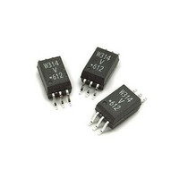
ACPL-W314-500E Avago Technologies US Inc., ACPL-W314-500E Datasheet - Page 14

ACPL-W314-500E
Manufacturer Part Number
ACPL-W314-500E
Description
OPTOCOUPLER IGBT 0.4A 6-SOIC
Manufacturer
Avago Technologies US Inc.
Specifications of ACPL-W314-500E
Output Type
Push-Pull, Totem-Pole
Package / Case
6-SOP
Voltage - Isolation
3750Vrms
Number Of Channels
1, Unidirectional
Current - Output / Channel
600mA
Propagation Delay High - Low @ If
300ns @ 7mA
Current - Dc Forward (if)
25mA
Input Type
DC
Mounting Type
Surface Mount
Fall Time
50 ns
Rise Time
50 ns
Configuration
1 Channel
Isolation Voltage
3750 Vrms
Maximum Propagation Delay Time
700 ns
Maximum Forward Diode Voltage
1.8 V
Minimum Forward Diode Voltage
1.2 V
Maximum Reverse Diode Voltage
5 V
Maximum Forward Diode Current
12 mA
Maximum Power Dissipation
250 mW
Maximum Operating Temperature
+ 100 C
Minimum Operating Temperature
- 40 C
Lead Free Status / RoHS Status
Lead free / RoHS Compliant
Available stocks
Company
Part Number
Manufacturer
Quantity
Price
Thermal Model for ACPL-P314/W314 Streched-SO6 Pack-
age Optocoupler
Definitions
R
R
R
R
P
P
T
T
T
ΔT
ΔT
Ambient Temperature: Junction to Ambient Thermal
Resistances were measured approximately 1.25cm above
optocoupler at ~23˚C in still air
For product information and a complete list of distributors, please go to our web site:
Avago, Avago Technologies, and the A logo are trademarks of Avago Technologies , in the United States and other countries.
Data subject to change. Copyright © 2005-2010 Avago Technologies. All rights reserved. Obsoletes AV01-0634EN
AV02-0158EN - December 10, 2010
a
11
12
21
22
1
2
1
2
:
:
:
:
:
1
2
: Junction to Ambient Thermal Resistance of LED due
: Junction to Ambient Thermal Resistance of LED due
: Junction to Ambient Thermal Resistance of Detec-
: Junction to Ambient Thermal Resistance of Detec-
: Temperature difference between LED junction and
: Temperature deference between Detector junction
to heating of LED
to heating of Detector (Output IC)
tor (Output IC) due to heating of LED.
tor (Output IC) due to heating of Detector (Output
IC).
Power dissipation of LED (W).
Power dissipation of Detector / Output IC (W).
Junction temperature of LED (˚C).
Junction temperature of Detector (˚C).
Ambient temperature.
ambient (˚C).
and ambient.
Description
This thermal model assumes that an 6-pin single-channel
plastic package optocoupler is soldered into a 7.62 cm x
7.62 cm printed circuit board (PCB). The temperature at
the LED and Detector junctions of the optocoupler can
be calculated using the equations below.
T
T
Notes:
1. Maximum junction temperature for above parts: 125 °C.
Jedec Specifications
low K board
high K board
www.avagotech.com
1
2
= (R
= (R
11
21
* P
* P
1
1
+ R
+ R
12
22
* P
* P
R
357
249
2
2
11
) + T
) + T
a
a
-- (1)
-- (2)
R
150, 166
76, 79
12
, R
21
R
228
159
22


