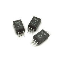
ACPL-W314-500E Avago Technologies US Inc., ACPL-W314-500E Datasheet - Page 4

ACPL-W314-500E
Manufacturer Part Number
ACPL-W314-500E
Description
OPTOCOUPLER IGBT 0.4A 6-SOIC
Manufacturer
Avago Technologies US Inc.
Specifications of ACPL-W314-500E
Output Type
Push-Pull, Totem-Pole
Package / Case
6-SOP
Voltage - Isolation
3750Vrms
Number Of Channels
1, Unidirectional
Current - Output / Channel
600mA
Propagation Delay High - Low @ If
300ns @ 7mA
Current - Dc Forward (if)
25mA
Input Type
DC
Mounting Type
Surface Mount
Fall Time
50 ns
Rise Time
50 ns
Configuration
1 Channel
Isolation Voltage
3750 Vrms
Maximum Propagation Delay Time
700 ns
Maximum Forward Diode Voltage
1.8 V
Minimum Forward Diode Voltage
1.2 V
Maximum Reverse Diode Voltage
5 V
Maximum Forward Diode Current
12 mA
Maximum Power Dissipation
250 mW
Maximum Operating Temperature
+ 100 C
Minimum Operating Temperature
- 40 C
Lead Free Status / RoHS Status
Lead free / RoHS Compliant
Available stocks
Company
Part Number
Manufacturer
Quantity
Price
Recommended Pb-Free IR Profile
Recommended reflow condition as per JEDEC Standard, J-STD-020 (latest revision). Non-Halide Flux should be used.
Regulatory Information
The ACPL-P314/W314 is approved by the following organizations:
IEC/EN/DIN EN 60747-5-2 (Option 060 only)
Approval under:
IEC 60747-5-5:2007
Table 1. IEC/EN/DIN EN 60747-5-2 Insulation Related Characteristics
*
** Refer to the following figure for dependence of P
4
Description
Installation classification per DIN VDE 0110/1.89, Table 1
Climatic Classification
Pollution Degree (DIN VDE 0110/1.89)
Maximum Working Insulation Voltage
Input to Output Test Voltage, Method b*
V
Partial Discharge < 5 pC,
Input to Output Test Voltage, Method a*
V
Partial Discharge < 5 pC
Highest Allowable Overvoltage*
(Transient Overvoltage, t
Safety Limiting Values
(Maximum values allowed in the event of a failure)
Insulation Resistance at T
IORM
IORM
Refer to the optocoupler section of the Isolation and Control Components Designer’s Catalog,
under Product Safety Regulations section, (IEC/EN/DIN EN 60747-5-2) for a detailed description
of Method a and Method b partial discharge test profiles.
for rated mains voltage d 150 Vrms
for rated mains voltage d 300 Vrms
for rated mains voltage d 450 Vrms
for rated mains voltage d 600 Vrms
for rated mains voltage d 1000 Vrms
Case Temperature
Input Current**
Output Power **
x 1.875 = V
x 1.6 = V
PR
, Type and sample test, t
PR
, 100% Production Test with t
ini
S
, V
= 60 sec)
IO
= 500 V
m
= 10 sec,
S
and I
m
= 1 sec
S
on ambient temperature.
UL
Approval under UL 1577 component recognition
program up to V
V
CSA
Approval under CSA Component Acceptance Notice #5,
File CA 88324.
ISO
Symbol
V
V
V
V
T
I
P
R
S,INPUT
S
IORM
PR
PR
IOTM
S,OUTPUT
S
= 5000 V
* (ACPL-P314/W314 Option 060)
RMS
ACPL-W14
I-IV
I-IV
I-IV
I-IV
I-III
55/100/21
2
1140
2137
1824
8000
175
d10
ISO
230
600
for the ACPL-W314, File E55361.
9
= 3750 V
800
700
600
500
400
300
200
100
0
0
T
25
S
RMS
– CASE TEMPERATURE – °C
50
ACPL-P314
I-IV
I-IV
I-III
I-III
55/100/21
2
891
1670
1426
6000
175
d10
230
600
for the ACPL-P314 and
75 100
9
125
P
I
S
150 175
S
(mA)
(mW)
Units
V
V
V
V
°C
mA
mW
:
peak
peak
peak
peak
200


