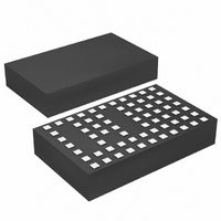
LTM4608EV#PBF Linear Technology, LTM4608EV#PBF Datasheet - Page 10

LTM4608EV#PBF
Manufacturer Part Number
LTM4608EV#PBF
Description
IC DC/DC UMODULE 8A 68-LGA
Manufacturer
Linear Technology
Series
µModuler
Type
Point of Load (POL) Non-Isolatedr
Datasheet
1.LTM4608IVPBF.pdf
(26 pages)
Specifications of LTM4608EV#PBF
Design Resources
LTM4608 Spice Model
Output
0.6 ~ 5 V
Number Of Outputs
1
Power (watts)
40W
Mounting Type
Surface Mount
Voltage - Input
2.7 ~ 5.5 V
Package / Case
68-LGA
1st Output
0.6 ~ 5 VDC @ 8A
Size / Dimension
0.59" L x 0.35" W x 0.11" H (15mm x 9mm x 2.8mm)
Power (watts) - Rated
40W
Operating Temperature
-40°C ~ 85°C
Efficiency
95%
Dc To Dc Converter Type
Step Down
Pin Count
68
Input Voltage
5.5V
Output Voltage
0.6 to 5V
Switching Freq
1.7MHz
Output Current
8A
Package Type
LGA
Output Type
Adjustable
Switching Regulator
Yes
Load Regulation
0.75%
Line Regulation
0.2%/V
Mounting
Surface Mount
Input Voltage (min)
2.375V
Operating Temperature Classification
Industrial
Lead Free Status / RoHS Status
Lead free / RoHS Compliant
3rd Output
-
2nd Output
-
Lead Free Status / Rohs Status
Compliant
Available stocks
Company
Part Number
Manufacturer
Quantity
Price
LTM4608
OPERATION
The typical LTM4608 application circuit is shown in Fig-
ure 18. External component selection is primarily deter-
mined by the maximum load current and output voltage.
Refer to Table 3 for specific external capacitor requirements
for a particular application.
V
There are restrictions in the maximum V
down ratio that can be achieved for a given input voltage.
The LTM4608 is 100% duty cycle, but the V
minimum dropout is a function of its load current. Please
refer to the curves in the Typical Performance Charac-
teristics section of this data sheet for more information.
Output Voltage Programming
The PWM controller has an internal 0.596V reference
voltage. As shown in the Block Diagram, a 10k/0.5%
internal feedback resistor connects V
together. The output voltage will default to 0.596V with
no feedback resistor. Adding a resistor R
to GND programs the output voltage:
Current mode control provides cycle-by-cycle fast current
limit and thermal shutdown in an overcurrent condition.
Internal overvoltage and undervoltage comparators pull
the open-drain PGOOD output low if the output feedback
voltage exits a ±10% window around the regulation point.
Pulling the RUN pin below 1.3V forces the controller into
its shutdown state, by turning off both M1 and M2 at low
load current. The TRACK pin is used for programming the
output voltage ramp and voltage tracking during start-up.
See Applications Information.
The LTM4608 is internally compensated to be stable over
all operating conditions. Table 3 provides a guideline
for input and output capacitances for several operating
conditions. The Linear Technology µModule Power De-
sign Tool is provided for transient and stability analysis.
APPLICATIONS INFORMATION
10
IN
V
to V
OUT
OUT
= 0.596V •
Step-Down Ratios
10k + R
R
FB
FB
OUT
IN
FB
to V
and FB pins
from FB pin
IN
OUT
to V
step-
OUT
The FB pin is used to program the output voltage with a
single external resistor to ground.
Multiphase operation can be easily employed with the
synchronization and phase mode controls. Up to 12 phases
can be cascaded to run simultaneously with respect to
each other by programming the PHMODE pin to different
levels. The LTM4608 has clock in and clock out for poly
phasing multiple devices or frequency synchronization.
High efficiency at light loads can be accomplished with
selectable Burst Mode operation using the MODE pin. These
light load features will accommodate battery operation.
Efficiency graphs are provided for light load operation in
the Typial Performance Characteristics.
Output voltage margining is supported, and can be pro-
gramed from ±5% to ±15% using the MGN and BSEL pins.
The PGOOD pin is disabled during margining.
Table 2. R
Input Capacitors
The LTM4608 module should be connected to a low AC
impedance DC source. Three 10µF ceramic capacitors
are included inside the module. Additional input capaci-
tors are only needed if a large load step is required up to
the 4A level. A 47µF to 100µF surface mount aluminum
electrolytic bulk capacitor can be used for more input bulk
capacitance. This bulk input capacitor is only needed if
the input source impedance is compromised by long in-
ductive leads, traces or not enough source capacitance.
If low impedance power planes are used, then this 47µF
capacitor is not needed.
For a buck converter, the switching duty-cycle can be
estimated as:
V
R
D =
OUT
FB
V
V
OUT
FB
0.596V
IN
Open
Resistor vs Output Voltage
1.2V
10k
6.65k
1.5V
4.87k
1.8V
3.09k
2.5V
2.21k
3.3V
4608fc


