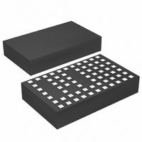
LTM4608EV#PBF Linear Technology, LTM4608EV#PBF Datasheet - Page 14

LTM4608EV#PBF
Manufacturer Part Number
LTM4608EV#PBF
Description
IC DC/DC UMODULE 8A 68-LGA
Manufacturer
Linear Technology
Series
µModuler
Type
Point of Load (POL) Non-Isolatedr
Datasheet
1.LTM4608IVPBF.pdf
(26 pages)
Specifications of LTM4608EV#PBF
Design Resources
LTM4608 Spice Model
Output
0.6 ~ 5 V
Number Of Outputs
1
Power (watts)
40W
Mounting Type
Surface Mount
Voltage - Input
2.7 ~ 5.5 V
Package / Case
68-LGA
1st Output
0.6 ~ 5 VDC @ 8A
Size / Dimension
0.59" L x 0.35" W x 0.11" H (15mm x 9mm x 2.8mm)
Power (watts) - Rated
40W
Operating Temperature
-40°C ~ 85°C
Efficiency
95%
Dc To Dc Converter Type
Step Down
Pin Count
68
Input Voltage
5.5V
Output Voltage
0.6 to 5V
Switching Freq
1.7MHz
Output Current
8A
Package Type
LGA
Output Type
Adjustable
Switching Regulator
Yes
Load Regulation
0.75%
Line Regulation
0.2%/V
Mounting
Surface Mount
Input Voltage (min)
2.375V
Operating Temperature Classification
Industrial
Lead Free Status / RoHS Status
Lead free / RoHS Compliant
3rd Output
-
2nd Output
-
Lead Free Status / Rohs Status
Compliant
Available stocks
Company
Part Number
Manufacturer
Quantity
Price
LTM4608
The LTM4608 device is an inherently current mode con-
trolled device. Parallel modules will have very good current
sharing. This will balance the thermals on the design. Tie
the I
evenly. To reduce ground potential noise, tie the I
of all LTM4608s together and then connect to the SGND at
only one point. Figure 19 shows a schematic of the parallel
design. The FB pins of the parallel module are tied together.
With parallel operation, input and output capacitors may
be reduced in part according to the operating duty cycle.
Input RMS Ripple Current Cancellation
Application Note 77 provides a detailed explanation of
multiphase operation. The input RMS ripple current can-
cellation mathematical derivations are presented, and a
graph is displayed representing the RMS ripple current
reduction as a function of the number of interleaved phases.
Figure 4 shows this graph.
14
APPLICATIONS INFORMATION
TH
pins of each LTM4608 together to share the current
Figure 4. Normalized Input RMS Ripple Current vs Duty Factor for One to Six Modules (Phases)
0.60
0.55
0.50
0.45
0.40
0.35
0.30
0.25
0.20
0.15
0.10
0.05
0
0.1 0.15 0.2 0.25 0.3 0.35 0.4 0.45 0.5 0.55 0.6 0.65 0.7 0.75 0.8 0.85 0.9
1-PHASE
2-PHASE
3-PHASE
4-PHASE
6-PHASE
THM
DUTY FACTOR (V
pins
Spread Spectrum Operation
Switching regulators can be particularly troublesome
where electromagnetic interference (EMI) is concerned.
Switching regulators operate on a cycle-by-cycle basis to
transfer power to an output. In most cases, the frequency
of operation is fixed based on the output load. This method
of conversion creates large components of noise at the
frequency of operation (fundamental) and multiples of the
operating frequency (harmonics).
To reduce this noise, the LTM4608 can run in spread
spectrum operation by tying the CLKIN pin to SV
In spread spectrum operation, the LTM4608’s internal
oscillator is designed to produce a clock pulse whose
period is random on a cycle-by-cycle basis but fixed
between 70% and 130% of the nominal frequency. This
has the benefit of spreading the switching noise over
a range of frequencies, thus significantly reducing the
O
/V
IN
)
4608 F04
4608fc
IN
.


