MA330012 Microchip Technology, MA330012 Datasheet - Page 180
MA330012
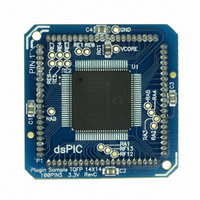
Manufacturer Part Number
MA330012
Description
MODULE DSPIC33 100P TO 84QFP
Manufacturer
Microchip Technology
Specifications of MA330012
Accessory Type
Plug-In Module (PIM) 80p - dsPIC33FJ256GP710
Kit Contents
DsPIC33 GP 100P To 80P TQFP Plug-In Module
Tool / Board Applications
General Purpose MCU, MPU, DSP, DSC
Silicon Manufacturer
Microchip
Core Architecture
DsPIC
Core Sub-architecture
DsPIC33
Silicon Core Number
DsPIC33F
Silicon Family Name
DsPIC33FJxxGPxxx
Rohs Compliant
Yes
For Use With
DsPICDEM 80-Pin Starter Board (DM300019)
Lead Free Status / RoHS Status
Lead free / RoHS Compliant
For Use With/related Products
dsPICDEM (DM300019)
Lead Free Status / RoHS Status
Lead free / RoHS Compliant, Lead free / RoHS Compliant


functions to the user. First, the control loop bandwidth is
buffered register. The PTPER buffer contents are loaded
dsPIC33F
15.1.4
In the Double Update mode (PTMOD<1:0> = 11), an
interrupt event is generated each time the PTMR regis-
ter is equal to zero, as well as each time a period match
occurs. The postscaler selection bits have no effect in
this mode of the timer.
The Double Update mode provides two additional
doubled because the PWM duty cycles can be updated,
twice per period. Second, asymmetrical center-aligned
PWM waveforms can be generated, which are useful for
minimizing output waveform distortion in certain motor
control applications.
15.1.5
The input clock to PTMR (F
options of 1:1, 1:4, 1:16 or 1:64, selected by control
bits, PTCKPS<1:0>, in the PTCON SFR. The prescaler
counter is cleared when any of the following occurs:
• a write to the PTMR register
• a write to the PTCON register
• any device Reset
The PTMR register is not cleared when PTCON is
written.
15.1.6
The match output of PTMR can optionally be post-
scaled through a 4-bit postscaler (which gives a 1:1 to
1:16 scaling).
The postscaler counter is cleared when any of the
following occurs:
• a write to the PTMR register
• a write to the PTCON register
• any device Reset
The PTMR register is not cleared when PTCON is written.
15.2
PTPER is a 15-bit register and is used to set the counting
period for the PWM time base. PTPER is a double-
into the PTPER register at the following instants:
• Free-Running and Single-Shot modes: When the
• Up/Down Count modes: When the PTMR register
The value held in the PTPER buffer is automatically
loaded into the PTPER register when the PWM time
base is disabled (PTEN = 0).
DS70165E-page 178
Note:
PTMR register is reset to zero after a match with
the PTPER register.
is zero.
PWM Period
DOUBLE UPDATE MODE
Programming a value of 0x0001 in the
PWM Period register could generate a
continuous interrupt pulse and hence,
must be avoided.
PWM TIME BASE PRESCALER
PWM TIME BASE POSTSCALER
OSC
/4) has prescaler
Preliminary
The
Equation 15-1:
EQUATION 15-1:
If the PWM time base is configured for one of the Up/
Down Count modes, the PWM period will be twice the
value provided by Equation 15-1.
The maximum resolution (in bits) for a given device
oscillator and PWM frequency can be determined using
Equation 15-2:
EQUATION 15-2:
15.3
Edge-aligned PWM signals are produced by the module
when the PWM time base is in Free-Running or Single-
Shot mode. For edge-aligned PWM outputs, the output
has a period specified by the value in PTPER and a duty
cycle specified by the appropriate Duty Cycle register
(see Figure 15-2). The PWM output is driven active at
the beginning of the period (PTMR = 0) and is driven
inactive when the value in the Duty Cycle register
matches PTMR.
If the value in a particular Duty Cycle register is zero,
then the output on the corresponding PWM pin will be
inactive for the entire PWM period. In addition, the out-
put on the PWM pin will be active for the entire PWM
period if the value in the Duty Cycle register is greater
than the value held in the PTPER register.
FIGURE 15-2:
PTPER
PWM
0
Edge-Aligned PWM
PTMR
Value
Resolution =
Duty Cycle
T
PWM
period
Period
=
(PTMR Prescale Value)
PWM PERIOD
PWM RESOLUTION
EDGE-ALIGNED PWM
T
can
© 2007 Microchip Technology Inc.
CY
log (2 • T
• (PTPER + 1)
New Duty Cycle Latched
be
log (2)
PWM
determined
/T
CY
)
using
Related parts for MA330012
Image
Part Number
Description
Manufacturer
Datasheet
Request
R

Part Number:
Description:
Manufacturer:
Microchip Technology Inc.
Datasheet:
Part Number:
Description:
Manufacturer:
Microchip Technology Inc.
Datasheet:
Part Number:
Description:
Manufacturer:
Microchip Technology Inc.
Datasheet:
Part Number:
Description:
Manufacturer:
Microchip Technology Inc.
Datasheet:
Part Number:
Description:
Manufacturer:
Microchip Technology Inc.
Datasheet:
Part Number:
Description:
Manufacturer:
Microchip Technology Inc.
Datasheet:
Part Number:
Description:
Manufacturer:
Microchip Technology Inc.
Datasheet:
Part Number:
Description:
Manufacturer:
Microchip Technology Inc.
Datasheet: