DLP-FPGA-M DLP Design Inc, DLP-FPGA-M Datasheet - Page 4
DLP-FPGA-M
Manufacturer Part Number
DLP-FPGA-M
Description
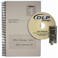
MODULE USB-TO-FPGA TOOL W/MANUAL
Manufacturer
DLP Design Inc
Datasheet
1.DLP-FPGA.pdf
(10 pages)
Specifications of DLP-FPGA-M
Main Purpose
Interface, USB to FPGA
Embedded
Yes, FPGA / CPLD
Utilized Ic / Part
FT2232D, XC3S250E-4TQ144
Primary Attributes
USB to FPGA, 40 I/O Pins, SRAM: 128k x 8
Secondary Attributes
4 Labs in Manual, 250k System Gates, 5.5k Logic Cells
Interface Type
USB, SPI
Product
Interface Modules
For Use With/related Products
XC3S250E-4TQ144
Lead Free Status / RoHS Status
Lead free / RoHS Compliant
Lead Free Status / RoHS Status
Lead free / RoHS Compliant, Lead free / RoHS Compliant
Other names
813-1009


5.0 JTAG INTERFACE
The easiest way to load an FPGA configuration (bit file) to the FPGA is to run the BitLoadApp
software, then select and program a file from the local hard drive directly to the SPI flash. Once
written to the SPI flash, the configuration will load to the FPGA and execute. Alternatively, a
traditional JTAG header location is provided on the DLP-FPGA giving the user access to the pins on
the FPGA required by the development tools. (Refer to the schematic at the end of this datasheet for
details.)
6.0 EEPROM SETUP / MPROG
The DLP-FPGA has a dual-channel USB interface to the host PC. Channel A is used exclusively to
load an FPGA configuration (bit file) to the SPI flash. This configuration data is automatically
transferred to the FPGA when power is applied to the module. Channel B is used for communication
between the FPGA and host PC at run time. A 93C56B EEPROM connected to the USB interface IC
is used to store the setup for the two channels. The parameters stored in the EEPROM include the
Vendor ID (VID), Product ID (PID), Serial Number, Description String, driver selection (VCP or D2XX)
and port type (UART serial or FIFO parallel).
As mentioned above, Channel A is used exclusively for loading the FPGA’s configuration to the SPI
flash, and Channel B is used for communication between the host PC and the DLP-FPGA. As such,
the D2XX drivers and FIFO mode must be selected in the EEPROM for Channel A. Channel B must
use the FIFO mode, but can use either the VCP or D2XX drivers. The VCP drivers make the DLP-
FPGA appear as an RS232 port to the host app. The D2XX drivers provide faster throughput, but
require working with a .lib or .dll library in the host app.
The operational modes and other EEPROM selections are written to the EEPROM using the MPROG
utility. This utility and its manual are available for download from the bottom of the page at
www.dlpdesign.com.
7.0 TEST BIT FILE
A test file is provided as a download from the DLP Design website that provides rudimentary access
to the I/O features of the DLP-FPGA.
The following features are provided:
This bit file is available from the DLP-FPGA’s download page.
Rev. 1.4 (November 2010)
•
•
•
•
•
Ping
Read the High/Low State of the Input-Only Pins
Drive I/O Pins High/Low or Read their High/Low State
Simple Loopback on Channel B
Simple Read/Write of Each Address in the SRAM
4
© DLP Design, Inc.
Related parts for DLP-FPGA-M
Image
Part Number
Description
Manufacturer
Datasheet
Request
R

Part Number:
Description:
MODULE USB-TO-TTL PARL FIFO CONV
Manufacturer:
DLP Design Inc
Datasheet:

Part Number:
Description:
KIT DEV DLP LIGHTCOMANDER
Manufacturer:
Logic
Datasheet:

Part Number:
Description:
MODULE DATA-ACQUISITION 8-CH
Manufacturer:
DLP Design Inc
Datasheet:

Part Number:
Description:
MODULE DATA-ACQUISITION 20-CH
Manufacturer:
DLP Design Inc
Datasheet:

Part Number:
Description:
RFID READER/WRITER SNGL-CH OEM
Manufacturer:
DLP Design Inc
Datasheet:

Part Number:
Description:
Interface Modules & Development Tools DLP-245PL PACKAGED w/CCS Compiler
Manufacturer:
DLP Design Inc

Part Number:
Description:
Interface Modules & Development Tools DLP-245PB-G BOARD + CCS Compiler
Manufacturer:
DLP Design Inc
Datasheet:

Part Number:
Description:
Interface Modules & Development Tools DLP-TILT SENSOR ACCEL VIBRATION
Manufacturer:
DLP Design Inc

Part Number:
Description:
MODULE USB-MCU FT245RL W/16F877A
Manufacturer:
DLP Design Inc
Datasheet:

Part Number:
Description:
MODULE USB-TO-FPGA TRAINING TOOL
Manufacturer:
DLP Design Inc
Datasheet:

Part Number:
Description:
MODULE USB-MCU FT232R W/18F2410
Manufacturer:
DLP Design Inc
Datasheet:

Part Number:
Description:
MODULE USB-MCU FT245RL W/SX48
Manufacturer:
DLP Design Inc
Datasheet:

Part Number:
Description:
MODULE USB-MCU FT2232D W/16F877A
Manufacturer:
DLP Design Inc
Datasheet:

Part Number:
Description:
MODULE USB-TO-FPGA SPARTAN3
Manufacturer:
DLP Design Inc
Datasheet:

Part Number:
Description:
MOD USB-MCU FT245RL W/18LF8722
Manufacturer:
DLP Design Inc
Datasheet: