IS-DEV KIT-8 NKK Switches, IS-DEV KIT-8 Datasheet - Page 8
IS-DEV KIT-8
Manufacturer Part Number
IS-DEV KIT-8
Description
SMARTSWITCH DEVELOPMENT KIT 8
Manufacturer
NKK Switches
Series
SmartSwitch™r
Datasheet
1.IS-DEV_KIT-8.pdf
(31 pages)
Specifications of IS-DEV KIT-8
Main Purpose
Switches with Programmable Display
Utilized Ic / Part
SmartSwitch™OLED Rocker Switch
Primary Attributes
OLED Rocker Switch
Description/function
SMARTSWITCH Development Kit
Maximum Operating Temperature
+ 70 C
Operating Voltage
2.7 V to 5.5 V
For Use With
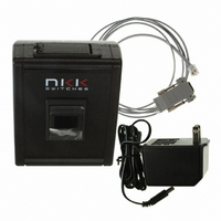
360-2431 - SERIAL CBL RJ11-DB9 FOR DEV KIT360-2430 - POWER SUPPLY 240VAC FOR DEV KIT360-2429 - POWER SUPPLY 120VAC FOR DEV KIT
Lead Free Status / RoHS Status
Contains lead / RoHS non-compliant
Secondary Attributes
-
Embedded
-
Lead Free Status / Rohs Status
Lead free / RoHS Compliant
For Use With/related Products
OLED Smartswitch Rocker
Other names
360-2421


7850 East Gelding Drive • Scottsdale, AZ 85260-3420
5. Programming the IS-Dev Kit-8
The IS-Dev Kit-8 communicates via RS232 with any communication software. The commands and protocol
will be explained in the sections 6 and 7.
This section covers programming the Dev Kit using the Universal Communicator.
The Universal Communicator handles all the communication protocol. Once the images are created, they can be
imported to the universal Communicator. The universal communicator allows attributes information to be
inputted. Once the images and attribute information are created, they can be downloaded to the Dev Kit. The
Dev Kit will function as programmed after the next power up or reset.
For how to use the software please refer to Universal Communicator documentation.
Creating OLED Rocker Images for Universal Communicator
The OLED Rocker display is 96x64 pixel monochrome. Images can be created graphically or by cropping from
a picture using graphic software such as Paint, Photoshop, etc. The images must be saved as 96x64
monochromatic bitmap files. The image files should be saved in a single folder. Universal Communicator
imports the files from the folder in alphanumeric order according to the file names. The file names should be
selected so the order of images will be as desired.
The Universal Communicator displays the image file names and assigned addresses for the controller. (Screen
shot 1)
These files can be downloaded to the controller.
IS-Dev Kit 8 Users Manual A.doc
5. Timer. The timer controls how fast to cycle through displaying the images sequentially. The timer
When the timer expires:
6 & 7 Reserved for future use and must be set to zero.
can be up to 65 seconds. The images change sequentially from the beginning address (the active
attribute address) to the end address (4)
A. If the timer is set to zero there will be no changes based on the timer.
B. If the timer is set to a positive number the timer starts running. If any of the switches are
Toll Free 1.877.2BUYNKK (877.228.9655) • Phone 480.991.0942 • Fax 480.998.1435
pressed, the timer gets reset. If a switch press causes a new image to be displayed the
attributes associated with the new image become active.
For each timer expire:
-
-
If the address of the image displayed is not equal to the End address (4):
If the address of the image being displayed is equal to the End address (4) then the
Middle address (2) of the End address (4) attribute block is checked.
ii. And the timer is reset and starts running again.
ii. If the Middle address (2) is a positive number the image at the address is
i. Then the next image is displayed. (The Attribute Block of the new image is
i. If the Middle address (2) is zero the image from the beginning address is
www.nkkswitches.com • Email engineering@nkkswitches.com
ignored.)
displayed. This will create a loop of the images from beginning address to end
address to be displayed until the a switch press causes a change
displayed and the attributes at the address become active.
IS-Dev Kit-8 User Manual
Page 8 of 31
1209
Related parts for IS-DEV KIT-8
Image
Part Number
Description
Manufacturer
Datasheet
Request
R

Part Number:
Description:
SMARTSWITCH DEVELOPMENT KIT 5C
Manufacturer:
NKK Switches
Datasheet:

Part Number:
Description:
KIT DEV FOR LCD 64X32 SWITCH
Manufacturer:
NKK Switches
Datasheet:

Part Number:
Description:
KIT DEV LCD 64X32 COMPACT SWITCH
Manufacturer:
NKK Switches
Datasheet:

Part Number:
Description:
KIT DEV FOR OLED DISPLAY
Manufacturer:
NKK Switches
Datasheet:

Part Number:
Description:
KIT DEV FOR OLED SWITCH
Manufacturer:
NKK Switches
Datasheet:

Part Number:
Description:
BOARD DEV 2RGB SW FLASH & PROGR
Manufacturer:
NKK Switches
Datasheet:

Part Number:
Description:
KIT DEV FOR LCD 64X32 DISPLAY
Manufacturer:
NKK Switches
Datasheet:

Part Number:
Description:
SMARTSWITCH DEVELOPMENT KIT 1
Manufacturer:
NKK Switches
Datasheet:

Part Number:
Description:
SMARTSWITCH DEVELOPMENT KIT 2
Manufacturer:
NKK Switches
Datasheet:

Part Number:
Description:
SMARTSWITCH DEVELOPMENT KIT 5
Manufacturer:
NKK Switches
Datasheet:

Part Number:
Description:
LED Displays PROGRAMMABLE SWITCH
Manufacturer:
NKK Switches

Part Number:
Description:
ON-OFF PLATE - SERIES -EMP
Manufacturer:
NKK Switches
Datasheet:

Part Number:
Description:
WRENCH SOCKET FOR KB SERIES PB
Manufacturer:
NKK Switches
Datasheet:

Part Number:
Description:
SWITCH TOGGLE DPST 25A SLDR 5PCS
Manufacturer:
NKK Switches
Datasheet:

Part Number:
Description:
SWITCH TOGGLE DPDT 15A SLDR 5PC
Manufacturer:
NKK Switches
Datasheet: