EVAL6574B STMicroelectronics, EVAL6574B Datasheet
EVAL6574B
Specifications of EVAL6574B
Available stocks


Related parts for EVAL6574B


EVAL6574B Summary of contents
Page 1
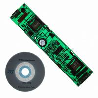
Electronic ballast with PFC using L6574 and L6561 Introduction Dedicated ICs for lamp ballast applications are now replacing the old solutions based on bipolar transistors driven by a saturable pulse transformer. The L6574 is a high-performance ballast driver, designed using ...
Page 2
Contents Contents 1 Half bridge converter for electronic lamp ballast . . . . . . . . . . . . . . . . . . 4 1.1 Lamp requirements . . . . . . . . ...
Page 3
AN993 List of figures Figure 1. Half bridge topology . . . . . . . . . . . . . . . . . . . . . . . . . . . . . . . ...
Page 4
Half bridge converter for electronic lamp ballast 1 Half bridge converter for electronic lamp ballast Voltage-fed, series-resonant half-bridge inverters are currently used for fluorescent lamps (Figure 1). This topology facilitates operation in zero voltage switching (ZVS) resonant mode, dramatically reducing ...
Page 5
AN993 2 L6574 ballast driver The L6574, whose internal block diagram is shown in power MOSFETs or IGBTs in half-bridge topology, ensuring all the features needed to properly drive and control a fluorescent bulb. Moreover, by varying the switching frequency, ...
Page 6
L6574 ballast driver Figure 3. Connection of a typical application CSupply Ref. Table 1. Description of device pins Number Name Preheat timing capacitor. The capacitor C shift time, according to the relations: t 1.5 s/ ∝F, K currents. During t ...
Page 7
AN993 Table 1. Description of device pins (continued) Number Name Enable 1. This pin (active high), forces the device into a latched shutdown state (like in undervoltage conditions). There are two ways of resuming normal operation: the first is by ...
Page 8
Device block description 3 Device block description The preheating control section and the bootstrap section are tightly linked to the application’s design. This chapter describes their workings and usage. 3.1 Preheating and ignition section The L6574’s turn-on sequence is divided ...
Page 9
AN993 That is to say: Equation 2 Figure 5. Timing block Figure 6. Timing oscillator block Cpre After the preheating time, the capacitor C by the current I , generating a second voltage ramp which feeds a transconductance fs amplifier, ...
Page 10
Device block description Where: Equation 4 R and R are the resistors connected to pin 4 and pin 2. ign pre At the end of the preheating time ( Equation 5 This means that the preheating frequency depends ...
Page 11
AN993 Equation 10 Equation 11 These equations fit well with the measured values, especially in the frequency range 100 kHz. Figure 8 ( 470 pF). f Figure 7. C pre shifting V(Cpre) freq preheating To ...
Page 12
Device block description 3.2 Control section The L6574 has two control functions, EN1 and EN2. Both functions are active high. To fully understand how these functions work, refer to ● EN1 (latched enable) is dedicated to stopping all device functions ...
Page 13
AN993 Figure 10. Startup timing diagram and EN2 function VSupply V(Cpre) EN2 3.3 Bootstrap section Bootstrap circuitry is needed to supply the high-voltage section. This function is normally accomplished by a high-voltage fast-recovery diode integrated structure replaces the external diode. ...
Page 14
Device block description If the HVG needs to be supplied for a long period of time, the C into account the leakage losses. The internal bootstrap driver has great advantages: the external fast-recovery diode can be avoided (it usually has ...
Page 15
AN993 4 Description of the demonstration application The design has been developed to drive a TL fluorescent lamp composed of two sections: the PFC, using the L6561 controller, and the ballast, based on the ...
Page 16
Description of the demonstration application Figure 14. PCB and components layouts 190mm 16/27 41mm Component layer Doc ID 5656 Rev 10 AN993 Solder layer AM01322v1 ...
Page 17
AN993 4.1 Power factor section Even if the PFC stage is not strictly necessary for electronic ballast applications, in this design it has been introduced for the following reasons. The PFC stage is necessary if the ballast input power is ...
Page 18
Description of the demonstration application The load consists of a series resonant circuit (L2-C18) with the lamp connected across the capacitor (C18). This topology allows operation in zero voltage switching mode, to reduce the transistor switching losses and the electromagnetic ...
Page 19
AN993 Figure 15. Current feedback loop Figure 16. Cpre waveform (Ch1) and amplifier output (Ch2) 4.5 Start-up and supply The start-up procedure is very important in an application that contains two different sections. The ballast section starts before the PFC, ...
Page 20
Description of the demonstration application 4.6 Safety circuitry In normal operation the inductive load ensures a zero voltage switching mode, but if the lamp is disconnected the switching losses in the power MOSFETs will increase considerably. To prevent this occurrence, ...
Page 21
AN993 5 Design tips 5.1 Inductance and capacitor evaluation To design an application with the L6574, a preliminary evaluation of the components can be done by fixing the lamp type and its electrical characteristics only. This evaluation is an "iterative" ...
Page 22
Design tips When the lamp is not yet ignited, C has to allow a sufficient current to flow into the lamp filament in order to preheat correctly. The power to be delivered to the lamp filaments (Pfil), the preheating frequency, ...
Page 23
AN993 Figure 21. Operating transfer function If one of these conditions is not verified, the evaluation process has to be redone changing the initial hypothesis (frequencies or assumption on the Cb ripple). If everything concords, the values found can be ...
Page 24
Dimming the lamp 6 Dimming the lamp The lamp is dimmed by changing the working frequency. The minimum working frequency is: Equation 18 To change the working frequency, one has to change the current that flows from pin 4. Using ...
Page 25
AN993 6.1 Dimming level and lamp turn-on During the start-up sequence the frequency always goes from f dimming level, and it is only after this that the lamp’s turn-on frequency moves towards higher frequencies. The delay during which f = ...
Page 26
Revision history 7 Revision history Table 3. Document revision history Date 21-Jun-2004 13-Jul-2009 26/27 Revision 9 Changed: figure and changed formula on the page 19 Document reformatted. 10 English reviewed. Modified: Equation 19 Doc ID 5656 Rev ...
Page 27
... AN993 Information in this document is provided solely in connection with ST products. STMicroelectronics NV and its subsidiaries (“ST”) reserve the right to make changes, corrections, modifications or improvements, to this document, and the products and services described herein at any time, without notice. All ST products are sold pursuant to ST’s terms and conditions of sale. ...