EVAL6574B STMicroelectronics, EVAL6574B Datasheet - Page 24
EVAL6574B
Manufacturer Part Number
EVAL6574B
Description
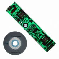
EVAL BOARD FOR HF TL BALLAST
Manufacturer
STMicroelectronics
Datasheet
1.EVAL6574B.pdf
(27 pages)
Specifications of EVAL6574B
Mfg Application Notes
EVAL6574B AppNote
Design Resources
EVAL6574B Gerber Files
Main Purpose
Lighting, Ballast Control
Embedded
No
Utilized Ic / Part
L6574
Primary Attributes
58W, 85 ~ 265 VAC, Dimmable, PFC
Secondary Attributes
Preheating Ignition
Processor To Be Evaluated
L6574
Operating Supply Voltage
600 V
Core Chip
L6574
Kit Contents
Board Docs
Development Tool Type
Hardware - Eval/Demo Board
Supported Devices
L6574 And L6562
Lead Free Status / RoHS Status
Contains lead / RoHS non-compliant
Other names
497-3823
Available stocks
Company
Part Number
Manufacturer
Quantity
Price


Dimming the lamp
6
24/27
Dimming the lamp
The lamp is dimmed by changing the working frequency. The minimum working frequency
is:
Equation 18
To change the working frequency, one has to change the current that flows from pin 4. Using
the circuitry shown in
amplifier’s out pin (pin 5) voltage: if V5 > V4, there will be no current in R
frequency will be equal to f
lower than V4, the current that flows from pin 4 will go into R
parallel between R
D
Equation 19
So the working frequency will be:
Equation 20
and the max f
For example, we can calculate a maximum frequency of ~53 kHz (V4 = 2 V and assuming
Vdiode3 = 0.5 V).
The dimming level is set by changing the value of the P1 potentiometer, which causes the
amplifier’s positive reference to change from 20-30 mV to 110-120 mV. If R16 is lowered, the
maximum working frequency is increased and the dimming level lowered as well (the higher
the frequency, the lower the current in the lamp’s arc).
If one tries to dim the lamp towards a low power range (<20% of the electrical arc power) a
common effect is the presence of stationary waves along the lamp tube and/or some
flickering effects.
A common trick to get rid of these disturbances is to add a small continuous current flow
inside the lamp (a few mA). The easiest way to do this is to add a resistor in parallel to the
half battery capacitor (C17 in
(I = 200 V/50 kΩ = 4 mA), which is already very effective. Of course, the resistor has to be
able to sustain the power dissipation caused by the current flow, so it is common to use
many resistors connected in parallel.
Remember that this is only a tip. It helps but is not enough, and should be used together
with the right frequency settings that must be chosen according to the type of lamp.
4
.
working
18
is obtained when V5 = 0 V.
and an equivalent resistor that depends on V
Figure
min
15, the current that flows from pin 4 also depends on the
Figure 13
. On the other hand, when the amplifier’s out voltage goes
Doc ID 5656 Rev 10
and
4
Figure
4
18). For instance, one can add 50 kΩ
16
and R
5
and on the voltage of
18
. Pin 4 sees the
16
and the
AN993
Related parts for EVAL6574B
Image
Part Number
Description
Manufacturer
Datasheet
Request
R

Part Number:
Description:
STMicroelectronics [RIPPLE-CARRY BINARY COUNTER/DIVIDERS]
Manufacturer:
STMicroelectronics
Datasheet:
Part Number:
Description:
STMicroelectronics [LIQUID-CRYSTAL DISPLAY DRIVERS]
Manufacturer:
STMicroelectronics
Datasheet:

Part Number:
Description:
BOARD EVAL FOR MEMS SENSORS
Manufacturer:
STMicroelectronics
Datasheet:
Part Number:
Description:
NPN TRANSISTOR POWER MODULE
Manufacturer:
STMicroelectronics
Datasheet:
Part Number:
Description:
TURBOSWITCH ULTRA-FAST HIGH VOLTAGE DIODE
Manufacturer:
STMicroelectronics
Datasheet:
Part Number:
Description:
Manufacturer:
STMicroelectronics
Datasheet:
Part Number:
Description:
DIODE / SCR MODULE
Manufacturer:
STMicroelectronics
Datasheet:
Part Number:
Description:
DIODE / SCR MODULE
Manufacturer:
STMicroelectronics
Datasheet:
Part Number:
Description:
Search -----> STE16N100
Manufacturer:
STMicroelectronics
Datasheet:
Part Number:
Description:
Search ---> STE53NA50
Manufacturer:
STMicroelectronics
Datasheet:
Part Number:
Description:
NPN Transistor Power Module
Manufacturer:
STMicroelectronics
Datasheet:
Part Number:
Description:
DIODE / SCR MODULE
Manufacturer:
STMicroelectronics
Datasheet: