OM6279,598 NXP Semiconductors, OM6279,598 Datasheet
OM6279,598
Specifications of OM6279,598
935283363598


Related parts for OM6279,598


OM6279,598 Summary of contents
Page 1
AN10315 LED dimmer demoboard Rev. 01 — 7 January 2005 Document information Info Content 2 Keywords I C, LED, RGB, LED controller, LED dimmer, LED blinker, color mixing, RGB mixing, RGB LED, White LED, Back lighting, GPIO, I/O expander, Keypad ...
Page 2
Philips Semiconductors Revision history Rev Date Description 01 20050107 Application note (9397 750 14062); initial version. Contact information For additional information, please visit: http://www.semiconductors.philips.com For sales office addresses, please send an email to: sales.addresses@www.semiconductors.philips.com 9397 750 14062 Application note Rev. ...
Page 3
Philips Semiconductors 1. Introduction The LED Dimmer Demoboard demonstrates the capability of the I keypad and perform Red/Green/Blue LED lighting color mixing operations. The demoboard is a stand alone solution using the Philips P89LV51RD2 microcontroller interfacing with a Philips PCA9564 ...
Page 4
Philips Semiconductors 3. Technical information—hardware 3.1 Block diagram Keypad Control Card RESET /INT /RESET Data / Control P89LV51 PCA RD2 9564 Fig 1. Block diagram 2 3.2 I C-bus device addresses Table 1: Device type P89LV51RD2/PCA9564PW PCA9531PW (Red - RGB ...
Page 5
Philips Semiconductors 3.3 Schematic 3.3.1 Keypad control card Fig 2. Keypad control card schematic 9397 750 14062 Application note PIN20 Rev. 01 — 7 January 2005 AN10315 LED dimmer demoboard GND2 GND © Koninklijke Philips Electronics N.V. 2005. All rights ...
Page 6
Philips Semiconductors 3.3.2 LED control card LD20 LD19 LD18 LD17 LD16 LD15 LD14 LD13 PIN16 V DD PIN8 V GND DD LD11 LD12 Fig 3. LED control card schematic 9397 750 14062 Application note PIN16 ...
Page 7
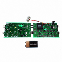
Philips Semiconductors 3.4 Demoboard (top view) 8 RGB LEDs: LD13 to LD18 PCA9533 PCA9531 Red PCA9531 Misc/Status Misc/Status LEDs: LD9, LD11, LD12 PCA9555 Keypad Fig 4. Schematic keypad control card 9397 750 14062 Application note Connectors for external master or ...
Page 8
Philips Semiconductors 3.5 RGB color mixing Red, Green and Blue are the 3 primary colors allowing creating all the other colors by mixing them together. The desired color is created by applying the right amount of Red, plus the right ...
Page 9
Philips Semiconductors 4. Technical information—how to use the demobord 4.1 Introduction Firmware in the P89LV51RD2 microcontroller emulates a cell phone application, programs fun patterns, and controls the brightness of a virtual display. A battery discharge emulation with a visual charge ...
Page 10
Power up or Reset Dialing Routine PROGRAMMING MODE YES Key F1 LD12 pushed? blinking NO EMULATION MODE YES Key F2 LD11 pushed? blinking NO Programming Fun Pattern 1 ...
Page 11
Philips Semiconductors 4.3 Dialing routine 4.3.1 How the keypad control works Keypad control is done using a PCA9555 with its INT signal connected to a GPIO of the P89LV51RD2 microcontroller. The 16 keys of the keypad are simply connected to ...
Page 12
Philips Semiconductors 4.3.3 Application: cell phone type keyboard—Dialing routine The firmware in the P89LV51RD2 targets a cell phone type application where the keypad is used to dial phone numbers and access to a programming mode in order to access the ...
Page 13
Philips Semiconductors 4.4 Programming mode The programming mode shows capabilities of the PCA9533 and the PCA9531 LED dimmers to control LEDs for: • RGB (Red / Green / Blue) color mixing • White LED brightness control Power supply used for ...
Page 14
Philips Semiconductors • Key 9: Blue (+) • Key 0: Speed (-) • Key #: Speed (+) Remark: Those keys have been programmed to detect a continuous push applied to them. When pushed continuously, (+) or (-) action is performed ...
Page 15
Philips Semiconductors 4.5 Emulation mode: battery discharge application Emulation mode can be described as a mode that would require external ‘stimulus’ to show an application in a real environment. The example in the firmware shows a simple application where a ...
Page 16
Philips Semiconductors 4.8 How to code messages are described using a ‘structure’ type definition where the I number of bytes to be sent/received and a pointer to a buffer with the data are used: typedef struct ...
Page 17
Philips Semiconductors I2C_WriteRepRead(&Message2,&Message3); // Function sending the I2C sequence After the read is performed Buffer3[0] and Buffer3[1] contain the input port register values. 5. Source code 5.1 i2cexpert.h //************************************************************************* // ...
Page 18
Philips Semiconductors #define PCA9531_G_RD 0xCD #define PCA9531_B_WR 0xCE #define PCA9531_B_RD 0xCF #define PCA9531_M_WR 0xC6 #define PCA9531_M_RD 0xC7 #define PCA9533_W_WR 0xC4 #define PCA9533_W_RD 0xC5 #define PCA24S08_WR 0xA0 #define PCA24S08_RD 0xA1 /**** Status Errors ****/ #define I2C_OK 0 #define I2C_BUSY 1 #define ...
Page 19
Philips Semiconductors static sbit LED0 = P2^2; static sbit LED1 = P2^3; static sbit LED2 = P2^4; static sbit LED3 = P2^5; static sbit PCA9555_Int = P3^2; sbit PCA9564_Reset = P3^4; 5.2 mainloop.c //************************************************************************* // ...
Page 20
Philips Semiconductors Message1.address = PCA9533_W_WR; Buffer1[0] = 0x11; // autoincrement + register 1 Buffer1[1] = 0x00; // default prescaler pwm0 Buffer1[2] = 0x10; // default duty cycle for pwm0 Buffer1[3] = 0x00; // default prescaler pwm1 Buffer1[4] = 0x10; // ...
Page 21
Philips Semiconductors void Init_GPIO(void) { Message2.address = PCA9555_WR; Message2.buf = Buffer2; Message2.nrBytes = 1; Buffer2[ subaddress = 0 Message3.address = PCA9555_RD; Message3.buf = Buffer3; Message3.nrBytes = 2; // read 2 bytes Buffer3[0] = 0xFF; Buffer3[1] = 0xFF; ...
Page 22
Philips Semiconductors { Fun_Pattern_Programming(); } if (Buffer3[0] == 0xF7) { Backlight_Programming(); } } Buffer3[1] = 0xFF; Message1.address = PCA9531_M_WR; // PCA9531 Misc Message1.nrBytes = 2; Buffer1[0] = 0x16; Buffer1[1] = 0x00; I2C_Write(&Message1 (Buffer3[1] == 0x7F) { Message1.address = ...
Page 23
Philips Semiconductors //**************************************************************************** // Main program //**************************************************************************** void main(void) { Init_PCA9564(); // Initialization PCA9564 Init_White(); // Initialization White LED's Init_RGB(); // Initialization RGB LED's Init_Misc(); // Initialization Misc LED's Init_GPIO(); // Initialization GPIO Intro_Patterns(); // Patterns displayed at power up ...
Page 24
Philips Semiconductors void InsertBigDelay(void) { InsertDelay(255); InsertDelay(255); InsertDelay(255); InsertDelay(255); InsertDelay(255); } //**************************************************************************** // Program the 3 PCA9531 (R/G/B) with the same parameter(s) //**************************************************************************** void Write_RGB_Controller(void) { Message1.address = PCA9531_R_WR; I2C_Write(&Message1); Message1.address = PCA9531_G_WR; I2C_Write(&Message1); Message1.address = PCA9531_B_WR; I2C_Write(&Message1); } //**************************************************************************** ...
Page 25
Philips Semiconductors { Trigger_GPIO_Polling = 1; } else { Trigger_GPIO_Polling = 0; Buffer3[0] = Snapshot_1_1st_Byte; Buffer3[1] = Snapshot_1_2nd_Byte (Trigger_GPIO_Polling == 1) { I2C_WriteRepRead(&Message2,&Message3 //**************************************************************************** // Pattern displayed at power up or after a reset //**************************************************************************** ...
Page 26
Philips Semiconductors Buffer1[1] = 0x00; Buffer1[2] = 0x0A; // LD18 @ BR0 Write_RGB_Controller(); InsertDelay(250); Buffer1[1] = 0x00; Buffer1[2] = 0x20; // LD19 @ BR0 Write_RGB_Controller(); InsertDelay(250); Buffer1[1] = 0x00; Buffer1[2] = 0xA0; // LD20 @ BR0 Write_RGB_Controller(); InsertDelay(250); Buffer1[1] = ...
Page 27
Philips Semiconductors if (Buffer3[1] != 0xFF & Nb_Key_Pressed < 11 & Buffer3[1] != 0xEF) // Key pushed = 9, 0 and != SND { Key_Pushed = Buffer3[1]; Nb_Key_Pressed++; One_To_Eight = 0; Nine_Zero = (Nb_Key_Pressed < 11 & ...
Page 28
Philips Semiconductors I2C_Write(&Message1); break (Nb_Key_Pressed == 11 & Buffer3[1] != 0xEF) // more than 10 keys pushed and SND not pushed yet { Buffer3[0] = 0xFF; Buffer3[1] = 0xFF; Buffer1[1] = 0xAA; I2C_Write(&Message1); Nb_Key_Pressed++; } if (Buffer3[1] ...
Page 29
Philips Semiconductors //**************************************************************************** // Function controlling the Duty Cycle for a specific device // inputs = Key "-", Key "+", I2C address // output = new Duty Cycle value //**************************************************************************** short int Duty_Cycle_Control(short int Operation, short int I2C_Address, short int ...
Page 30
Philips Semiconductors { GPIO_Interrupt_Handler(); InsertDelay(100); if (Buffer3[0] == 0xFD) Duty_Cycle_White = Duty_Cycle_Control(Decrement, PCA9533_W_WR, Duty_Cycle_White); if (Buffer3[0] == 0xFB) Duty_Cycle_White = Duty_Cycle_Control(Increment, PCA9533_W_WR, Duty_Cycle_White); } Buffer3[1] = 0xFF; GPIO_Polling_On = 0; Message1.address = PCA9531_M_WR; Message1.nrBytes = 2; Buffer1[0] = 0x15; Buffer1[1] ...
Page 31
Philips Semiconductors case 2: Buffer1[1] = 0x08; Buffer1[2] = 0x00; break; case 3: Buffer1[1] = 0x20; Buffer1[2] = 0x00; break; case 4: Buffer1[1] = 0x80; Buffer1[2] = 0x00; break; case 5: Buffer1[1] = 0x00; Buffer1[2] = 0x02; break; case 6: ...
Page 32
Philips Semiconductors //**************************************************************************** // Function controlling the Fun Pattern programming // 3 programmable patterns: color and speed // Entered by pushing 4 // Key 1 = select pattern 1 // Key 4 = select pattern 2 // Key 7 = ...
Page 33
Philips Semiconductors if (Buffer3[0] == 0xDF) Duty_Cycle_G_One = Duty_Cycle_Control(Increment, PCA9531_G_WR, Duty_Cycle_G_One); if (Buffer3[0] == 0x7F) Duty_Cycle_B_One = Duty_Cycle_Control(Decrement, PCA9531_B_WR, Duty_Cycle_B_One); if (Buffer3[1] == 0xFE) Duty_Cycle_B_One = Duty_Cycle_Control(Increment, PCA9531_B_WR, Duty_Cycle_B_One); if (Buffer3[1] == 0xFD & Speed_One > Speed_One--; } ...
Page 34
Philips Semiconductors if (Buffer3[1] == 0xF7 & Speed_Two < 255) { Speed_Two++; } Speed_Prog_On = 0; GPIO_Polling_On = 0; } Buffer3[1] = 0xFF; Message1.address = PCA9531_M_WR; Message1.nrBytes = 2; Buffer1[0] = 0x15; Buffer1[1] = 0x00; I2C_Write(&Message1 (Buffer3[0] == ...
Page 35
Philips Semiconductors I2C_Write(&Message1); } Message1.address = PCA9531_R_WR; Message1.nrBytes = 3; Buffer1[0] = 0x15; Buffer1[1] = 0x00; Buffer1[2] = 0x00; I2C_Write(&Message1); Message1.address = PCA9531_G_WR; I2C_Write(&Message1); Message1.address = PCA9531_B_WR; I2C_Write(&Message1); Buffer3[1] = 0xFF; } //**************************************************************************** // Function emulating a Battery Discharge // ...
Page 36
Philips Semiconductors Buffer1[0] = 0x12; Buffer1[1] = 0x80; Buffer1[2] = 0x97; Buffer1[3] = 0x08; Buffer1[4] = 0x50; Buffer1[5] = 0x3A; I2C_Write(&Message1 (Battery_Level == 0x40) { Message1.address = PCA9531_M_WR; // PCA9531 Misc Message1.nrBytes = 6; Buffer1[0] = 0x12; Buffer1[1] ...
Page 37
Philips Semiconductors //**************************************************************************** // Auto demo mode // Reset only allows leaving this mode //**************************************************************************** void Auto_Demo(void) { int i; int j; int k; Message1.buf = Buffer1; Message1.nrBytes = 7; Message1.address = PCA9531_R_WR; Buffer1[0] = 0x11; // autoincrement + register ...
Page 38
Philips Semiconductors // Animation 2 Buffer1[1] = 0xAA; // LD13-16 @ BR0 Buffer1[2] = 0xAA; // LD17-20 @ BR0 Write_RGB_Controller(); InsertBigDelay(); Buffer1[1] = 0xAB; // LD13 @ BR1 - LD14-16 @ BR0 Buffer1[2] = 0xAA; // LD17-20 @ BR0 Write_RGB_Controller(); ...
Page 39
Philips Semiconductors Buffer1[1] = 0xEA; // LD16@BR1, LD13-14-15@BR0 Buffer1[2] = 0xEA; // LD20@BR1, LD17-18-19@BR0 Write_RGB_Controller(); InsertBigDelay(); } // Animation 4 Buffer1[1] = 0x00; // LD13-16 Buffer1[2] = 0x00; // LD17-20 Write_RGB_Controller(); for ( < 3; i++) { ...
Page 40
Philips Semiconductors Buffer1[2] = 0x00; // default duty cycle for pwm0 Buffer1[3] = 0x00; // default prescaler pwm1 Buffer1[4] = 0x00; // default duty cycle for pwm1 Buffer1[5] = 0xAA; // Green RGB LED's = BR0 Buffer1[6] = 0xAA; // ...
Page 41
Philips Semiconductors Buffer1[1] = 0x00 blue I2C_Write(&Message1); // Some color mixing 1 Message1.address = PCA9531_R_WR; Buffer1[1] = 0x36; I2C_Write(&Message1); Message1.address = PCA9531_G_WR; Buffer1[1] = 0x2B; I2C_Write(&Message1); Message1.address = PCA9531_B_WR; for (k = 0x00; k < 0xFF; k++) { ...
Page 42
Philips Semiconductors I2C_Write(&Message1); InsertDelay(40); }; Message1.address = PCA9531_G_WR; for (j = 0x00; j < 0xFF; j++) { Buffer1[ I2C_Write(&Message1); InsertDelay(40); }; Buffer1[1] = 0x00; I2C_Write(&Message1); Message1.address = PCA9531_B_WR; for (k = 0x00; k < 0xFF; k++) { Buffer1[1] ...
Page 43
Philips Semiconductors }; Message1.address = PCA9531_G_WR; for (j = 0x00; j < 0xFF; j++) { Buffer1[ I2C_Write(&Message1); InsertDelay(40 END OF THE I2C ROUTINES // 9397 750 14062 Application note // Increase amount of green Rev. ...
Page 44
Philips Semiconductors 6. Disclaimers Life support — These products are not designed for use in life support appliances, devices, or systems where malfunction of these products can reasonably be expected to result in personal injury. Philips Semiconductors customers using or ...
Page 45
Philips Semiconductors 8. Contents 1 Introduction . . . . . . . . . . . . . . . . . . . . . . . . . . . . 3 2 Ordering information . . ...