OM6279,598 NXP Semiconductors, OM6279,598 Datasheet - Page 16
OM6279,598
Manufacturer Part Number
OM6279,598
Description
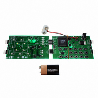
DEMO BOARD LED DIMMER
Manufacturer
NXP Semiconductors
Datasheet
1.OM6279598.pdf
(45 pages)
Specifications of OM6279,598
Main Purpose
Lighting, RGB LED Controller
Embedded
Yes, MCU, 8-Bit
Utilized Ic / Part
PCA9564PW, PCA9555PW, PCA9531PW, PCA9533DP/01
Primary Attributes
I2C Bus Controller, 1 8-Bit GPIO, 1 8-Bit LED Dimmer
Secondary Attributes
Different Demonstration Programs Through MCU
Lead Free Status / RoHS Status
Not applicable / Not applicable
Other names
568-4003
935283363598
935283363598


Philips Semiconductors
9397 750 14062
Application note
4.8 How to code I
I
number of bytes to be sent/received and a pointer to a buffer with the data are used:
typedef struct
{
} I2C_MESSAGE;
The user must then use a variable with an ‘I2C_MESSAGE’ type and a variable acting as
a buffer that will be filled with the message to send (Write operation) or filled with the
message received (Read operation).
Example 1: Program the PCA9531_Red with BR0 at (max frequency, 50 % duty cycle)
idata I2C_MESSAGE
idata BYTE Buffer1[16];
Message1.nrBytes = 7;
Message1.buf
Message1.address = 0xCA;
Buffer1[0]
Buffer1[1]
Buffer1[2]
Buffer1[3]
Buffer1[4]
Buffer1[5]
Buffer1[6]
I2C_Write(&Message1);
Example 2: Read the PCA9555 Input port Registers. To perform this operation a Write to
idata I2C_MESSAGE Message2;
data I2C_MESSAGE
idata BYTE Buffer2[16];
idata BYTE Buffer3[16];
Message2.nrBytes = 1;
Message3.nrBytes = 2
Message2.buf
Message3.buf
Message2.address = 0x46;
Message3.address = 0x47;
Buffer2[0] = 0x00;
2
C messages are described using a ‘structure’ type definition where the I
BYTE
BYTE
BYTE
address;
nrBytes;
*buf;
and BR1 at (max frequency, 10 % duty cycle), with LD13 to LD16 blinking at
BR0 and LD17 to LD20 blinking at BR1.
the device must been initiated first in order to provide the command code (or
pointer information) to decide which register(s) needs to be read. Then a
read is performed.
2
= Buffer2;
= Buffer3;
C commands using the P89LV51RD2/PCA9564
= Buffer1;
= 0x11;
= 0x00;
= 0x80;
= 0x00;
= 0x19;
= 0x00;
= 0x00;
Message3;
Message1;
Rev. 01 — 7 January 2005
// slave address to sent/receive message
// number of bytes in message buffer
// pointer to application message buffer
// I2C address PCA9531 Red (RGB LEDs)
// auto increment + register 1
// max frequency
// 50 % duty cycle
// max frequency
// 10 % duty cycle
// Red RGB LED's = off
// Red RGB LED's = off
// Function sending the I2C sequence
// The 1st message is 1 byte long
// The 2nd message is 2 bytes long;
// I2C address PCA9555 Write
// I2C address PCA9555 Read
// Set the command byte / pointer
1st part of the message)
© Koninklijke Philips Electronics N.V. 2005. All rights reserved.
LED dimmer demoboard
AN10315
2
C address, the
16 of 45
Related parts for OM6279,598
Image
Part Number
Description
Manufacturer
Datasheet
Request
R

Part Number:
Description:
Display Modules & Development Tools LED EVAL Board
Manufacturer:
NXP Semiconductors

Part Number:
Description:
NXP Semiconductors designed the LPC2420/2460 microcontroller around a 16-bit/32-bitARM7TDMI-S CPU core with real-time debug interfaces that include both JTAG andembedded trace
Manufacturer:
NXP Semiconductors
Datasheet:

Part Number:
Description:
NXP Semiconductors designed the LPC2458 microcontroller around a 16-bit/32-bitARM7TDMI-S CPU core with real-time debug interfaces that include both JTAG andembedded trace
Manufacturer:
NXP Semiconductors
Datasheet:
Part Number:
Description:
NXP Semiconductors designed the LPC2468 microcontroller around a 16-bit/32-bitARM7TDMI-S CPU core with real-time debug interfaces that include both JTAG andembedded trace
Manufacturer:
NXP Semiconductors
Datasheet:
Part Number:
Description:
NXP Semiconductors designed the LPC2470 microcontroller, powered by theARM7TDMI-S core, to be a highly integrated microcontroller for a wide range ofapplications that require advanced communications and high quality graphic displays
Manufacturer:
NXP Semiconductors
Datasheet:
Part Number:
Description:
NXP Semiconductors designed the LPC2478 microcontroller, powered by theARM7TDMI-S core, to be a highly integrated microcontroller for a wide range ofapplications that require advanced communications and high quality graphic displays
Manufacturer:
NXP Semiconductors
Datasheet:
Part Number:
Description:
The Philips Semiconductors XA (eXtended Architecture) family of 16-bit single-chip microcontrollers is powerful enough to easily handle the requirements of high performance embedded applications, yet inexpensive enough to compete in the market for hi
Manufacturer:
NXP Semiconductors
Datasheet:
Part Number:
Description:
The XA-S3 device is a member of Philips Semiconductors? XA(eXtended Architecture) family of high performance 16-bitsingle-chip microcontrollers
Manufacturer:
NXP Semiconductors
Datasheet:

Part Number:
Description:
The NXP BlueStreak LH75401/LH75411 family consists of two low-cost 16/32-bit System-on-Chip (SoC) devices
Manufacturer:
NXP Semiconductors
Datasheet:
Part Number:
Description:
The NXP LPC3130/3131 combine an 180 MHz ARM926EJ-S CPU core, high-speed USB2
Manufacturer:
NXP Semiconductors
Datasheet:
Part Number:
Description:
The NXP LPC3141 combine a 270 MHz ARM926EJ-S CPU core, High-speed USB 2
Manufacturer:
NXP Semiconductors
Part Number:
Description:
The NXP LPC3143 combine a 270 MHz ARM926EJ-S CPU core, High-speed USB 2
Manufacturer:
NXP Semiconductors

Part Number:
Description:
The NXP LPC3152 combines an 180 MHz ARM926EJ-S CPU core, High-speed USB 2
Manufacturer:
NXP Semiconductors
Part Number:
Description:
The NXP LPC3154 combines an 180 MHz ARM926EJ-S CPU core, High-speed USB 2
Manufacturer:
NXP Semiconductors