RDK-201 Power Integrations, RDK-201 Datasheet
RDK-201
Specifications of RDK-201


Related parts for RDK-201


RDK-201 Summary of contents
Page 1
... The products and applications illustrated herein (including transformer construction and circuits external to the products) may be covered by one or more U.S. and foreign patents, or potentially by pending U.S. and foreign patent applications assigned to Power Integrations. A complete list of Power Integrations' patents may be found at www.powerint.com. Power Integrations grants its customers a license under certain patent rights as set forth at < ...
Page 2
... Although this board is designed to satisfy safety isolation requirements, the engineering prototype has not been agency approved. Therefore, all testing should be performed using an isolation transformer to provide the AC input to the prototype board. Power Integrations Tel: +1 408 414 9200 Fax: +1 408 414 9201 www.powerint.com ...
Page 3
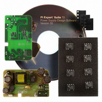
... LNK625PG. The document contains the power supply specification, schematic, bill of materials, transformer documentation, printed circuit layout, and performance data. Figure 1 – Populated Circuit Board Photograph. Page RDR-201 6 W LinkSwitch-CV Adapter Power Integrations Tel: +1 408 414 9200 Fax: +1 408 414 9201 www.powerint.com ...
Page 4
... Required average efficiency at 25, 50, 75 and 100 % of P OUT Measured average efficiency Environmental Conducted EMI Safety Line Surge Differential Mode (L1-L2) Common mode (L1/L2-PE) Ambient Temperature Power Integrations Tel: +1 408 414 9200 Fax: +1 408 414 9201 www.powerint.com Symbol Min Typ Max V 90 265 IN ...
Page 5
... Schematic Page RDR-201 6 W LinkSwitch-CV Adapter Figure 2 – Schematic Tel: +1 408 414 9200 Fax: +1 408 414 9201 Power Integrations www.powerint.com ...
Page 6
... During U1’s off time, the energy stored in the transformer is transferred to the secondary side, delivering current to both the output capacitors and the load. Power Integrations Tel: +1 408 414 9200 Fax: +1 408 414 9201 www.powerint.com This filtering, together with the integrated switching ...
Page 7
... R5 is chosen to supply the necessary BP pin current. Capacitor C4 is the BP pin capacitor and should be placed as close as possible to the BP pin and source pins of the device. Page RDR-201 6 W LinkSwitch-CV Adapter Power Integrations Tel: +1 408 414 9200 Fax: +1 408 414 9201 www.powerint.com ...
Page 8
... The AC input is located away from switching nodes to minimize noise coupling that may bypass input filtering. 6 Place C4 (the bypass capacitor) as close as possible to the BYPASS pin on U1. Figure 3 – Printed Circuit Layout, dimensions in mils (one thousandth of an inch). Power Integrations Tel: +1 408 414 9200 Fax: +1 408 414 9201 www.powerint.com 11-Nov-08 Page ...
Page 9
... CFR-12JB-8K2 Yageo ERJ-3GEYJ120V Panasonic ERJ-6GEYJ180V Panasonic ERJ-6GEYJ821V Panasonic CRF253-4 10R Vitrohm PM-9820 Ho Jinn Plastic Elect. Co. Santronics SNX R1494 Wurth Electronics 750811016 Ice Components TP08152 Precision Electronics 019-6361-00R LNK625PG Power Integrations Power Integrations Tel: +1 408 414 9200 Fax: +1 408 414 9201 www.powerint.com ...
Page 10
... Triple Insulated wire: #27 TIW [6] Tape: 3M 1298 Polyester Film, 2 mils thick, 8.6 mm wide. [7] Varnish Power Integrations Tel: +1 408 414 9200 Fax: +1 408 414 9201 www.powerint.com Figure 4 – Transformer Electrical Diagram. 1 second, 60 Hz, from Pins1-2 to Pins 6-9 Pins 1-2, all other windings open Pins 1-2, all other windings open Pins 1-2, with Pins 6,9,3 and 5 shorted ...
Page 11
... Apply 2 layers of tape item [6] Assembly Assemble core halves and tape together after properly gapping center leg of core. Finish Dip Varnish Page RDR-201 6 W LinkSwitch-CV Adapter Figure 5 – Transformer Build Diagram. Tel: +1 408 414 9200 Fax: +1 408 414 9201 Power Integrations www.powerint.com ...
Page 12
... ACDC_LNK-CV_102208_Rev1-1.xls; LinkSwitch-CV Continuous/Discontinuous Flyback Transformer Design Spreadsheet RDK-201 Adapter Design Minimum AC Input Voltage Maximum AC Input Voltage AC Mains Frequency Output Voltage Output Power Efficiency Estimate Loss Allocation Factor Bridge Rectifier Conduction Time Estimate Input Filter Capacitor Chosen LinkSwitch-CV device ...
Page 13
... Typical (Nominal) Primary Inductance 10 Tolerance of Primary inductance 115 Primary Winding Number of Turns 126 nH/T^2 Gapped Core Effective Inductance Maximum Flux Density, (BM<2500) Calculated at typical current limit and typical primary 2474 Gauss inductance Tel: +1 408 414 9200 Fax: +1 408 414 9201 Power Integrations www.powerint.com ...
Page 14
... AWGS DIAS ODS INSS VOLTAGE STRESS PARAMETERS VDRAIN PIVB PIVS Power Integrations Tel: +1 408 414 9200 Fax: +1 408 414 9201 www.powerint.com Peak Flux Density, (BP<3100) Calculated at maximum current limit and maximum primary 2887 Gauss inductance AC Flux Density for Core Loss Curves (0.5 X ...
Page 15
... Average 73.2 US EISA (2007) 66.1 requirement 69.5 requirement Table 1 – Efficiency Table. Tel: +1 408 414 9200 Fax: +1 408 414 9201 115 VAC 230 VAC 1200 1400 230 VAC 73.6 74.3 73.6 72.5 73.5 Power Integrations www.powerint.com ...
Page 16
... The test method can be found here: http://www.energystar.gov/ia/partners/prod_development/downloads/power_supplies/EP SupplyEffic_TestMethod_0804.pdf For the latest up to date information please visit the PI Green Room: http://www.powerint.com/greenroom/regulations.htm Power Integrations Tel: +1 408 414 9200 Fax: +1 408 414 9201 www.powerint.com Minimum active mode efficiency is defined as the 11-Nov-08 Page ...
Page 17
... California). Page RDR-201 6 W LinkSwitch-CV Adapter ) Minimum Efficiency in Active Mode of Operation O 0.5 × P 0.09 × 0. natural logarithm Maximum Power for No-load ) O AC-DC EPS ≤ 0.5 W Tel: +1 408 414 9200 Fax: +1 408 414 9201 st , 2008 must meet minimum 0.5 O Power Integrations www.powerint.com ...
Page 18
... Active Mode Efficiency Low Voltage Models (V Nameplate Output (P ≤ > ≤ > No-load Energy Consumption (both models) Nameplate Output ( < ≥ ≤ 250 W Power Integrations Tel: +1 408 414 9200 Fax: +1 408 414 9201 www.powerint.com st , 2008. ) Minimum Efficiency in Active Mode of Operation O 0.48 × P 0.0626 × ...
Page 19
... Figure 8 – Load Regulation, Room Temperature. Page RDR-201 6 W LinkSwitch-CV Adapter 115 140 165 190 Input Voltage (VAC) 400 600 800 Output Current (mA) Tel: +1 408 414 9200 Fax: +1 408 414 9201 215 240 265 90 VAC 265 VAC 1000 1200 Power Integrations www.powerint.com ...
Page 20
... Figure 9 – Line Regulation, Room Temperature, Full Load. Power Integrations Tel: +1 408 414 9200 Fax: +1 408 414 9201 www.powerint.com 140 165 190 Line Voltage (VAC) 11-Nov-08 215 240 265 Page ...
Page 21
... The ambient temperature within the box was monitored by a T-type thermocouple placed above the power supply. The temperature of the Power Integrations device, U1, was monitored by soldering a T-type thermocouple to one of the middle source pins, close to the case. The temperature of the ...
Page 22
... Figure 12 – 90 VAC, Full Load. Upper 100 V, 2 µs / div. DRAIN Middle div. FB Lower 0 div. DRAIN Power Integrations Tel: +1 408 414 9200 Fax: +1 408 414 9201 www.powerint.com Figure 11 – 265 VAC, Full Load. Upper 200 V, 2 µs / div. DRAIN Lower 0 div. DRAIN Figure 13 – ...
Page 23
... Page RDR-201 6 W LinkSwitch-CV Adapter Figure 15 – Start-up Profile, 265 VAC, Full Load div. Figure 17 – 265 VAC Input and Full Load. Upper 200 div. DRAIN Lower 0 div. DRAIN Power Integrations Tel: +1 408 414 9200 Fax: +1 408 414 9201 www.powerint.com ...
Page 24
... Figure 18 – Transient Response, 90 VAC 75-100-75% Load Step. Upper: Output Voltage 10 mV div. Bottom: Load Current, 0 div. Power Integrations Tel: +1 408 414 9200 Fax: +1 408 414 9201 www.powerint.com Figure 19 – Transient Response, 265 VAC 75-100-75% Load Step. Upper: Load Current div. ...
Page 25
... Figure 21 – Oscilloscope Probe with Probe Master (www.probemaster.com) 4987A BNC Adapter. (Modified with wires for ripple measurement, and two parallel decoupling capacitors added) Page RDR-201 6 W LinkSwitch-CV Adapter Probe Ground Probe Tip Power Integrations Tel: +1 408 414 9200 Fax: +1 408 414 9201 www.powerint.com ...
Page 26
... RDR-201 6 W LinkSwitch-CV Adapter 11.5.2 Measurement Results Figure 22 – Ripple, 90 VAC, Full Load div. Power Integrations Tel: +1 408 414 9200 Fax: +1 408 414 9201 www.powerint.com Figure 23 – 265 VAC, Full Load div. 11-Nov-08 Page ...
Page 27
... Unit passes under all test conditions. Page RDR-201 6 W LinkSwitch-CV Adapter Injection Injection Location Phase (° ( ( Tel: +1 408 414 9200 Fax: +1 408 414 9201 Test Result (10 Strikes Pass/Fail) Pass Pass Pass Pass Power Integrations www.powerint.com ...
Page 28
... RDR-201 6 W LinkSwitch-CV Adapter 13 Conducted EMI Figure 24 – Worst Case Conducted EMI, Maximum Steady State Load, 230 VAC, 60 Hz, and EN55022 B Power Integrations Tel: +1 408 414 9200 Fax: +1 408 414 9201 www.powerint.com Limits, Artificial Hand. 11-Nov-08 Page ...
Page 29
... Revision History Date Author 11-Nov-08 TS Page RDR-201 6 W LinkSwitch-CV Adapter Revision Description & changes 1.5 Initial Release Tel: +1 408 414 9200 Fax: +1 408 414 9201 Reviewed SGK, PV Power Integrations www.powerint.com ...
Page 30
... RDR-201 6 W LinkSwitch-CV Adapter Power Integrations Tel: +1 408 414 9200 Fax: +1 408 414 9201 www.powerint.com Notes 11-Nov-08 Page ...
Page 31
... Page RDR-201 6 W LinkSwitch-CV Adapter Notes Power Integrations Tel: +1 408 414 9200 Fax: +1 408 414 9201 www.powerint.com ...
Page 32
... RDR-201 6 W LinkSwitch-CV Adapter For the latest updates, visit our website: www.powerint.com Power Integrations reserves the right to make changes to its products at any time to improve reliability or manufacturability. Power Integrations does not assume any liability arising from the use of any device or circuit described herein. POWER INTEGRATIONS MAKES NO WARRANTY HEREIN AND SPECIFICALLY DISCLAIMS ALL WARRANTIES INCLUDING, WITHOUT LIMITATION, THE IMPLIED WARRANTIES OF MERCHANTABILITY, FITNESS FOR A PARTICULAR PURPOSE, AND NON-INFRINGEMENT OF THIRD PARTY RIGHTS ...