EVL6566A-75WADP STMicroelectronics, EVL6566A-75WADP Datasheet - Page 9
EVL6566A-75WADP
Manufacturer Part Number
EVL6566A-75WADP
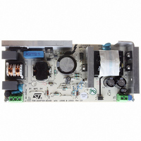
Description
BOARD EVAL FOR L6566A
Manufacturer
STMicroelectronics
Type
Power Factor Correctionr
Datasheets
1.L6566ATR.pdf
(51 pages)
2.TSM1014IDT.pdf
(10 pages)
3.L6563ATR.pdf
(39 pages)
4.EVL6566A-75WADP.pdf
(8 pages)
Specifications of EVL6566A-75WADP
Main Purpose
AC/DC, Primary and Secondary Side with PFC
Outputs And Type
1, Isolated
Power - Output
75W
Voltage - Output
19V
Current - Output
4A
Voltage - Input
90 ~ 264VAC
Frequency - Switching
65kHz
Board Type
Fully Populated
Utilized Ic / Part
L6563, L6566A, TSM1014
Input Voltage
90 V to 264 V
Output Voltage
19 V
Dimensions
78 mm x 174 mm
Product
Power Management Modules
Lead Free Status / RoHS Status
Lead free / RoHS Compliant
Regulator Topology
-
Lead Free Status / Rohs Status
Lead free / RoHS Compliant
For Use With/related Products
L6563, L6566A
Other names
497-6449
Available stocks
Company
Part Number
Manufacturer
Quantity
Price


L6566A
Table 1.
N°
10
5
6
7
8
9
Vcc_PFC
COMP
VREF
Vcc
DIS
Pin
CS
Pin functions (continued)
Supply voltage of both the signal part of the IC and the gate driver. The internal
high voltage generator charges an electrolytic capacitor connected between this
pin and GND (pin 3) as long as the voltage on the pin is below the turn-on threshold
of the IC, after that it is disabled and the chip is turned on. The IC is disabled as the
voltage on the pin falls below the UVLO threshold. This threshold is reduced at light
load to counteract the natural reduction of the self-supply voltage. Sometimes a
small bypass capacitor (0.1 µF typ.) to GND might be useful to get a clean bias
voltage for the signal part of the IC.
Supply pin output. This pin is intended for supplying the PFC controller IC in
systems comprising a PFC pre-regulator or other compatible circuitry. It is internally
connected to the Vcc pin (5) via a controlled switch. The switch is closed as the IC
starts up and opens when the voltage at pin COMP is lower than a threshold (light
load), whenever the IC is shut down (either latched or not) and during UVLO. If not
used, the pin will be left floating.
Input to the PWM comparator. The current flowing in the MOSFET is sensed
through a resistor, the resulting voltage is applied to this pin and compared with an
internal reference to determine MOSFET’s turn-off. The pin is equipped with 150 ns
min. blanking time after the gate-drive output goes high for improved noise
immunity. A second comparison level located at 1.5 V latches the device off and
reduces its consumption in case of transformer saturation or secondary diode short
circuit. The information is latched until the voltage on the Vcc pin (5) goes below
the UVLO threshold, hence resulting in intermittent operation. A logic circuit
improves sensitivity to temporary disturbances.
IC’s latched disable input. Internally the pin connects a comparator that, when the
voltage on the pin exceeds 4.5 V, latches off the IC and brings its consumption to a
lower value. The latch is cleared as the voltage on the Vcc pin (5) goes below the
UVLO threshold, but the HV generator keeps the Vcc voltage high (see pin 1
description). It is then necessary to recycle the input power to restart the IC. For a
quick restart pull pin 16 (AC_OK) below the disable threshold (see pin 16
description). Bypass the pin with a capacitor to GND (pin 3) to reduce noise pick-
up. Ground the pin if the function is not used.
Control input for loop regulation. The pin will be driven by the phototransistor
(emitter-grounded) of an optocoupler to modulate its voltage by modulating the
current sunk. A capacitor placed between the pin and GND (3), as close to the IC
as possible to reduce noise pick-up, sets a pole in the output-to-control transfer
function. The dynamics of the pin is in the 2.5 to 5 V range. A voltage below an
internally defined threshold activates burst-mode operation. The voltage at the pin
is bottom-clamped at about 2 V. If the clamp is externally overridden and the
voltage is pulled below 1.4 V the IC will shut down.
An internal generator furnishes an accurate voltage reference (5 V ± 2 %) that can
be used to supply few mA to an external circuit. A small film capacitor (0.1 µF typ.),
connected between this pin and GND (3), is recommended to ensure the stability of
the generator and to prevent noise from affecting the reference. This reference is
internally monitored by a separate auxiliary reference and any failure or drift will
cause the IC to latch off.
Function
Pin settings
9/51
Related parts for EVL6566A-75WADP
Image
Part Number
Description
Manufacturer
Datasheet
Request
R

Part Number:
Description:
BOARD DEMO FOR L6563/LL6566A
Manufacturer:
STMicroelectronics
Datasheet:

Part Number:
Description:
STMicroelectronics [RIPPLE-CARRY BINARY COUNTER/DIVIDERS]
Manufacturer:
STMicroelectronics
Datasheet:
Part Number:
Description:
STMicroelectronics [LIQUID-CRYSTAL DISPLAY DRIVERS]
Manufacturer:
STMicroelectronics
Datasheet:

Part Number:
Description:
BOARD EVAL FOR MEMS SENSORS
Manufacturer:
STMicroelectronics
Datasheet:
Part Number:
Description:
NPN TRANSISTOR POWER MODULE
Manufacturer:
STMicroelectronics
Datasheet:
Part Number:
Description:
TURBOSWITCH ULTRA-FAST HIGH VOLTAGE DIODE
Manufacturer:
STMicroelectronics
Datasheet:
Part Number:
Description:
Manufacturer:
STMicroelectronics
Datasheet:
Part Number:
Description:
DIODE / SCR MODULE
Manufacturer:
STMicroelectronics
Datasheet:
Part Number:
Description:
DIODE / SCR MODULE
Manufacturer:
STMicroelectronics
Datasheet:
Part Number:
Description:
Search -----> STE16N100
Manufacturer:
STMicroelectronics
Datasheet:
Part Number:
Description:
Search ---> STE53NA50
Manufacturer:
STMicroelectronics
Datasheet:
Part Number:
Description:
NPN Transistor Power Module
Manufacturer:
STMicroelectronics
Datasheet: