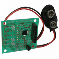
AS5045 AB austriamicrosystems, AS5045 AB Datasheet - Page 13

AS5045 AB
Manufacturer Part Number
AS5045 AB
Description
BOARD ADAPTER AS5045
Manufacturer
austriamicrosystems
Specifications of AS5045 AB
Sensor Type
Magnetic, Rotary Position
Sensing Range
360°
Interface
Serial
Voltage - Supply
9V
Embedded
No
Utilized Ic / Part
AS5045
Lead Free Status / RoHS Status
Lead free by exemption / RoHS compliant by exemption
Sensitivity
-
AS5045
Data Sheet
8 Mode Input Pin
The mode input pin activates or deactivates an internal filter that is used to reduce the analog output noise.
Activating the filter (Mode pin = LOW) provides a reduced output noise of 0.03° rms. At the same time, the output
delay is increased to 384µs. This mode is recommended for high precision, low speed applications.
Deactivating the filter (Mode pin = HIGH) reduces the output delay to 96µs and provides an output noise of 0.06°
rms. This mode is recommended for higher speed applications.
The MODE pin should be set at power-up. A change of the mode during operation is not allowed.
Switching the Mode pin affects the following parameters:
Table 2. Slow and Fast Mode Parameters 12-bit Absolute Angular Position Output
8.1 Synchronous Serial Interface (SSI)
Figure 5. Synchronous Serial Interface with Absolute Angular Position Data
If CSn changes to logic low, Data Out (DO) will change from high impedance (tri-state) to logic high and the read-out
will be initiated.
www.austriamicrosystems.com
Parameter
Sampling rate
Transition noise (1 sigma)
Output delay
Max. speed @ 4096 samples/rev.
Max. speed @ 1024 samples/rev.
Max. speed @ 256 samples/rev.
Max. speed @ 64 samples/rev.
CSn
CLK
After a minimum time t
Each subsequent rising CLK edge shifts out one bit of data.
The serial word contains 18 bits, the first 12 bits are the angular information D[11:0], the subsequent 6 bits
contain system information, about the validity of data such as OCF, COF, LIN, Parity and Magnetic Field status
(increase/decrease).
A subsequent measurement is initiated by a “high” pulse at CSn with a minimum duration of t
DO
t
DO active
t
CLK FE
1
D11
T
t
CLK/2
DO valid
D10
CLK FE,
D9
data is latched into the output shift register with the first falling edge of CLK.
D8
D7
Angular Position Data
2.61 kHz (384 µs)
Slow Mode (Mode = low)
≤ 0.03° rms
384µs
38 rpm
153 rpm
610 rpm
2441 rpm
D6
D5
8
D4
Revision 1.7
D3
D2
D1
D0
OCF COF
Fast Mode (Mode = high, VDD5V)
10.42 kHz (96µs)
≤ 0.06° rms
96µs
153 rpm
610 rpm
2441 rpm
9766 rpm
Status Bits
LIN
Mag
INC
DEC
Mag
18
Even
PAR
t
DO Tristate
t
CSn
CSn.
t
CLK FE
1
D11
13 – 33


