AS5045 AB austriamicrosystems, AS5045 AB Datasheet - Page 21
AS5045 AB
Manufacturer Part Number
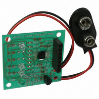
AS5045 AB
Description
BOARD ADAPTER AS5045
Manufacturer
austriamicrosystems
Specifications of AS5045 AB
Sensor Type
Magnetic, Rotary Position
Sensing Range
360°
Interface
Serial
Voltage - Supply
9V
Embedded
No
Utilized Ic / Part
AS5045
Lead Free Status / RoHS Status
Lead free by exemption / RoHS compliant by exemption
Sensitivity
-


AS5045
Data Sheet
Figure 13. OTP Register Analog Read
12 Alignment Mode
The alignment mode simplifies centering the magnet over the center of the chip to gain maximum accuracy.
Alignment mode can be enabled with the falling edge of CSn while Prog = logic high (Figure 14). The Data bits
D11-D0 of the SSI change to a 12-bit displacement amplitude output. A high value indicates large X or Y
displacement, but also higher absolute magnetic field strength. The magnet is properly aligned, when the difference
between highest and lowest value over one full turn is at a minimum.
Under normal conditions, a properly aligned magnet will result in a reading of less than 128 over a full turn.
The MagINCn and MagDECn indicators will be = 1 when the alignment mode reading is < 128. At the same time,
both hardware pins MagINCn (#1) and MagDECn (#2) will be pulled to VSS. A properly aligned magnet will therefore
produce a MagINCn = MagDECn = 1 signal throughout a full 360° turn of the magnet.
Stronger magnets or short gaps between magnet and IC may show values larger than 128. These magnets are still
properly aligned as long as the difference between highest and lowest value over one full turn is at a minimum.
The alignment mode can be reset to normal operation by a power-on-reset (disconnect / re-connect power supply) or
by a falling edge on CSn with Prog = low.
www.austriamicrosystems.com
Figure 14. Enabling the Alignment Mode
Prog
CSn
PROG
CSn
CLK
2µs
min.
2µs
min.
ProgEN
AlignMode enable
t
LoadProg
OutpEN
Internal
test bit
digital
Prog changes to Output
Read-out
V
via SSI
ref
halfEN
PWM
1
Comp
Mag
EN
Revision 1.7
PWM
Dis
CLK
Z0
Analog Readback Data at PROG
Aread
V
V
programmed
unprogrammed
Figure 15. Exiting Alignment Mode
Prog
CSn
Z7
Z8
exit AlignMode
Z9
Z10
Z11
CCW
16
Power-on-
Reset;
turn off
supply
Read-out
via SSI
21 – 33
Related parts for AS5045 AB
Image
Part Number
Description
Manufacturer
Datasheet
Request
R

Part Number:
Description:
IC ENCODER PROG 12-BIT 16-SSOP
Manufacturer:
austriamicrosystems
Datasheet:

Part Number:
Description:
BOARD DEMO AS5045
Manufacturer:
austriamicrosystems
Datasheet:
Part Number:
Description:
IC ENCODER PROG 12-BIT 16-SSOP
Manufacturer:
austriamicrosystems
Datasheet:
Part Number:
Description:
12-bit Programmable Magnetic Rotary Encoder
Manufacturer:
austriamicrosystems
Datasheet:
Part Number:
Description:
BOARD PROGRAM AS5040
Manufacturer:
austriamicrosystems
Datasheet:
Part Number:
Description:
IC SWITCH QUAD SPST 14-TSSOP
Manufacturer:
austriamicrosystems
Datasheet:
Part Number:
Description:
IC SWITCH QUAD SPST 14-TSSOP
Manufacturer:
austriamicrosystems
Datasheet:
Part Number:
Description:
IC AMP AUDIO MONO 1.8W 10-MSOP
Manufacturer:
austriamicrosystems
Datasheet:
Part Number:
Description:
IC AMP AUDIO MONO 1.8W 10-MSOP
Manufacturer:
austriamicrosystems
Datasheet:
Part Number:
Description:
IC AMP AUDIO MONO 1.8W 10-MSOP
Manufacturer:
austriamicrosystems
Datasheet:
Part Number:
Description:
IC AMP AUD 1.8W 3DB GAIN 10-MSOP
Manufacturer:
austriamicrosystems
Datasheet:
Part Number:
Description:
IC DRIVER LED 8-DIGIT 24-SOIC
Manufacturer:
austriamicrosystems
Datasheet:
Part Number:
Description:
IC DRIVER LED 8-DIGIT 24-SOIC
Manufacturer:
austriamicrosystems
Datasheet:
Part Number:
Description:
IC, LINE/SPEAKER PHONE CIRCUIT, SOIC-28
Manufacturer:
austriamicrosystems
Datasheet:
Part Number:
Description:
IC MULTI-STANDARD CMOS TELEPHONE SOIC-28
Manufacturer:
austriamicrosystems
Datasheet: