AS5045 AB austriamicrosystems, AS5045 AB Datasheet - Page 15
AS5045 AB
Manufacturer Part Number
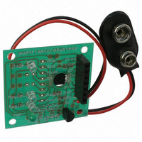
AS5045 AB
Description
BOARD ADAPTER AS5045
Manufacturer
austriamicrosystems
Specifications of AS5045 AB
Sensor Type
Magnetic, Rotary Position
Sensing Range
360°
Interface
Serial
Voltage - Supply
9V
Embedded
No
Utilized Ic / Part
AS5045
Lead Free Status / RoHS Status
Lead free by exemption / RoHS compliant by exemption
Sensitivity
-


AS5045
Data Sheet
Table 5. Magnetic Field Strength Red-yellow-green Indicator (OTP option)
Note: Pin 1 (MagINCn) and pin 2 (MagDECn) are active low via open drain output and require an external pull-up
resistor. If the magnetic field is in range, both outputs are turned off.
The two pins may also be combined with a single pull-up resistor. In this case, the signal is high when the magnetic
field is in range. It is low in all other cases (see Table 4 and Table 5).
8.2 Daisy Chain Mode
The Daisy Chain mode allows connection of several AS5045’s in series, while still keeping just one digital input for
data transfer (see “Data IN” in Figure 6 below). This mode is accomplished by connecting the data output (DO; pin 9)
to the data input (PROG; pin 8) of the subsequent device. An RC filter must be implemented between each PROG
pin of device n and DO pin of device n+1, to prevent then encoders to enter the alignment mode, in case of ESD
discharge, long cables, not conform signal levels or shape. Using the values R=100R and C=1nF allow a max. CLK
frequency of 1MHz on the whole chain. The serial data of all connected devices is read from the DO pin of the first
device in the chain. The length of the serial bit stream increases with every connected device, it is
The last data bit of the first device (Parity) is followed by a dummy bit and the first data bit of the second device
(D11), etc… (see Figure 7)
Figure 6. Daisy Chain Hardware Configuration
www.austriamicrosystems.com
Mag
All other combinations
INC
0
1
1
Status Bits
n * (18+1) bits:
e.g. 38 bit for two devices, 57 bit for three devices, etc…
DEC
Mag
0
1
1
LIN
0
0
1
Hardware Pins
INCn
Mag
n/a
Off
On
On
DECn
Mag
n/a
Off
Off
On
OTP: Mag CompEn = 1 (red-yellow-green programming
option)
Description
No distance change
Magnetic input field OK (GREEN range, ~45…75mT)
YELLOW range: magnetic field is ~ 25…45mT or ~75…135mT. The
AS5045 may still be operated in this range, but with slightly reduced
accuracy.
RED range: magnetic field is ~<25mT or >~135mT. It is still possible to
operate the AS5045 in the red range, but not recommended.
Not available
Revision 1.7
15 – 33
Related parts for AS5045 AB
Image
Part Number
Description
Manufacturer
Datasheet
Request
R

Part Number:
Description:
IC ENCODER PROG 12-BIT 16-SSOP
Manufacturer:
austriamicrosystems
Datasheet:

Part Number:
Description:
BOARD DEMO AS5045
Manufacturer:
austriamicrosystems
Datasheet:
Part Number:
Description:
IC ENCODER PROG 12-BIT 16-SSOP
Manufacturer:
austriamicrosystems
Datasheet:
Part Number:
Description:
12-bit Programmable Magnetic Rotary Encoder
Manufacturer:
austriamicrosystems
Datasheet:
Part Number:
Description:
BOARD PROGRAM AS5040
Manufacturer:
austriamicrosystems
Datasheet:
Part Number:
Description:
IC SWITCH QUAD SPST 14-TSSOP
Manufacturer:
austriamicrosystems
Datasheet:
Part Number:
Description:
IC SWITCH QUAD SPST 14-TSSOP
Manufacturer:
austriamicrosystems
Datasheet:
Part Number:
Description:
IC AMP AUDIO MONO 1.8W 10-MSOP
Manufacturer:
austriamicrosystems
Datasheet:
Part Number:
Description:
IC AMP AUDIO MONO 1.8W 10-MSOP
Manufacturer:
austriamicrosystems
Datasheet:
Part Number:
Description:
IC AMP AUDIO MONO 1.8W 10-MSOP
Manufacturer:
austriamicrosystems
Datasheet:
Part Number:
Description:
IC AMP AUD 1.8W 3DB GAIN 10-MSOP
Manufacturer:
austriamicrosystems
Datasheet:
Part Number:
Description:
IC DRIVER LED 8-DIGIT 24-SOIC
Manufacturer:
austriamicrosystems
Datasheet:
Part Number:
Description:
IC DRIVER LED 8-DIGIT 24-SOIC
Manufacturer:
austriamicrosystems
Datasheet:
Part Number:
Description:
IC, LINE/SPEAKER PHONE CIRCUIT, SOIC-28
Manufacturer:
austriamicrosystems
Datasheet:
Part Number:
Description:
IC MULTI-STANDARD CMOS TELEPHONE SOIC-28
Manufacturer:
austriamicrosystems
Datasheet: