AS5045 AB austriamicrosystems, AS5045 AB Datasheet - Page 14
AS5045 AB
Manufacturer Part Number
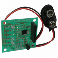
AS5045 AB
Description
BOARD ADAPTER AS5045
Manufacturer
austriamicrosystems
Specifications of AS5045 AB
Sensor Type
Magnetic, Rotary Position
Sensing Range
360°
Interface
Serial
Voltage - Supply
9V
Embedded
No
Utilized Ic / Part
AS5045
Lead Free Status / RoHS Status
Lead free by exemption / RoHS compliant by exemption
Sensitivity
-


AS5045
Data Sheet
8.1.1
D11:D0 absolute angular position data (MSB is clocked out first)
OCF (Offset Compensation Finished), logic high indicates the finished Offset Compensation Algorithm
COF (Cordic Overflow), logic high indicates an out of range error in the CORDIC part. When this bit is set, the data
at D9:D0 is invalid. The absolute output maintains the last valid angular value.
This alarm may be resolved by bringing the magnet within the X-Y-Z tolerance limits.
LIN (Linearity Alarm), logic high indicates that the input field generates a critical output linearity.
When this bit is set, the data at D9:D0 may still be used, but can contain invalid data. This warning may be resolved
by bringing the magnet within the X-Y-Z tolerance limits.
Even Parity bit for transmission error detection of bits 1…17 (D11…D0, OCF, COF, LIN, MagINC, MagDEC)
Placing the magnet above the chip, angular values increase in clockwise direction by default.
Data D11:D0 is valid, when the status bits have the following configurations:
Table 3. Status Bit Outputs
*) MagInc=MagDec=1 is only recommended in YELLOW mode (see Table 5)
8.1.2
The AS5045 provides several options of detecting movement and distance of the magnet in the Z-direction. Signal
indicators MagINCn and MagDECn are available both as hardware pins (pins 1 and 2) and as status bits in the serial
data stream (see Figure 5). Additionally, an OTP programming option is available with bit MagCompEn (see
Figure 10) that enables additional features:
In the default state, the status bits MagINC, MagDec and pins MagINCn, MagDECn have the following function:
Table 4. Magnetic Field Strength Variation Indicator
When bit MagCompEn is programmed in the OTP, the function of status bits MagINC, MagDec and pins MagINCn,
MagDECn is changed to the following function:
www.austriamicrosystems.com
OCF
Mag
INC
Status Bits
1
0
0
1
1
Data Content
Z-axis Range Indication (Push Button Feature, Red/Yellow/Green Indicator)
COF
DEC
Mag
0
0
1
0
1
Hardware Pins
INCn
Mag
LIN
Off
Off
On
On
0
DECn
Mag
Off
On
Off
On
Mag
INC
1*)
0
0
1
OTP: Mag CompEn = 0 (default)
Description
No distance change
Magnetic input field OK (in range, ~45…75mT)
Distance increase; pull-function. This state is dynamic and only active while
the magnet is moving away from the chip.
Distance decrease; push- function. This state is dynamic and only active
while the magnet is moving towards the chip.
Magnetic field is ~<45mT or >~75mT. It is still possible to operate the
AS5045 in this range, but not recommended
Revision 1.7
Mag
DEC
1*)
0
1
0
Parity
Even checksum of bits 1:15
14 – 33
Related parts for AS5045 AB
Image
Part Number
Description
Manufacturer
Datasheet
Request
R

Part Number:
Description:
IC ENCODER PROG 12-BIT 16-SSOP
Manufacturer:
austriamicrosystems
Datasheet:

Part Number:
Description:
BOARD DEMO AS5045
Manufacturer:
austriamicrosystems
Datasheet:
Part Number:
Description:
IC ENCODER PROG 12-BIT 16-SSOP
Manufacturer:
austriamicrosystems
Datasheet:
Part Number:
Description:
12-bit Programmable Magnetic Rotary Encoder
Manufacturer:
austriamicrosystems
Datasheet:
Part Number:
Description:
BOARD PROGRAM AS5040
Manufacturer:
austriamicrosystems
Datasheet:
Part Number:
Description:
IC SWITCH QUAD SPST 14-TSSOP
Manufacturer:
austriamicrosystems
Datasheet:
Part Number:
Description:
IC SWITCH QUAD SPST 14-TSSOP
Manufacturer:
austriamicrosystems
Datasheet:
Part Number:
Description:
IC AMP AUDIO MONO 1.8W 10-MSOP
Manufacturer:
austriamicrosystems
Datasheet:
Part Number:
Description:
IC AMP AUDIO MONO 1.8W 10-MSOP
Manufacturer:
austriamicrosystems
Datasheet:
Part Number:
Description:
IC AMP AUDIO MONO 1.8W 10-MSOP
Manufacturer:
austriamicrosystems
Datasheet:
Part Number:
Description:
IC AMP AUD 1.8W 3DB GAIN 10-MSOP
Manufacturer:
austriamicrosystems
Datasheet:
Part Number:
Description:
IC DRIVER LED 8-DIGIT 24-SOIC
Manufacturer:
austriamicrosystems
Datasheet:
Part Number:
Description:
IC DRIVER LED 8-DIGIT 24-SOIC
Manufacturer:
austriamicrosystems
Datasheet:
Part Number:
Description:
IC, LINE/SPEAKER PHONE CIRCUIT, SOIC-28
Manufacturer:
austriamicrosystems
Datasheet:
Part Number:
Description:
IC MULTI-STANDARD CMOS TELEPHONE SOIC-28
Manufacturer:
austriamicrosystems
Datasheet: